
Logic Probe Plans

The construction requires a ballpoint pen that can be unscrewed in the middle, has a wide barrel, and is made of plastic to prevent short circuits. A dual op-amp with high sensitivity, excellent rail-to-rail characteristics, a large input impedance, and an output current exceeding 20 mA is necessary; the Radio Shack part number 276-1715 is suitable for this purpose.
To prepare the pen, the ink cartridge should be removed, and any residual ink cleaned out. The probe tip must be soldered to resistors R2 and R3, which are then epoxied into the bottom of the pen. While the epoxy cures, the top section of the pen should be modified for the LED by drilling a mounting hole if required, alongside a smaller hole for the power leads. The rest of the circuit should be assembled as illustrated in the provided schematic using wire wrap wire, ensuring the assembly remains compact. Approximately three feet of loose wire should be left for the alligator clips, which should not yet be connected.
Once the epoxy has cured, R2 and R3 should be connected to the remaining circuit components. To test the assembly, connect the first alligator clip wire to the positive terminal of a five-volt power supply and the second clip to the negative terminal. The LED should remain off initially. When the probe tip is touched to the positive terminal, the LED should illuminate red, and when touched to the negative terminal, it should light green. If the LED exhibits inverted behavior, the polarity should be reversed. Should the LED fail to light, the wiring should be inspected, and if issues persist, the op-amp may need to be replaced with a compatible model.
After successful testing, the circuit can be mounted inside the ballpoint pen. The three feet of loose wire for the alligator clips should be fed through the smaller hole near the pen's top, ensuring proper identification of each wire. The red alligator clip is then soldered to one wire, and the black clip to the other. The LED should be inserted into its designated hole and secured with epoxy. Finally, the pen can be reassembled, and a final test conducted. If functionality is confirmed, the assembly is complete.
The logic probe is user-friendly. To measure the voltage at a specific point in a logic circuit, the alligator clips must first be connected to the circuit’s power supply. The probe tip can then be placed at the desired test point. The LED will illuminate green for voltages less than 9/20 of the power supply voltage and red for voltages exceeding 11/20 of the power supply voltage. A high-frequency signal will cause the LED to alternate between red and green, appearing orange.This is a set of plans for an inexpensive, high performance digital logic probe that you can build in a few hours. It is small enough to use a plastic ball-point pen as a chassis, giving it a personalized touch and added style.
The main advantage of this design is that the LED will only light when the probe tip is touching a voltage source (not fl oating). This is a necessary feature when working with tri-state logic, and is overlooked by most logic probe plans found in textbooks. Ball-point pen - This will be the housing for the logic probe. Chose a pen that unscrews at the middle, has a large barrel, and is made of plastic. (Metal will cause short-circuits, unless you are really careful. ) Dual op-amp - Chose an op-amp that is sensitive, has good rail-to-rail characteristics, a large input impedance, and an output current greater than 20 mA.
Radio Shack part number 276-1715 should work well. Prepare the pen by removing the ink cartridge and by cleaning out any ink residue. Solder the probe tip to R2 and R3 as shown in the schematic and epoxy this assembly into the bottom of the pen. While the epoxy dries, prepare the top half of the pen for the LED by drilling a mounting hole if necessary.
Drill another smaller hole in the side of the pen for the power leads to enter. Assemble the rest of the circuit as shown in the schematic above with wire wrap wire. Try to keep it as small as possible. Leave about 3 feet of loose wire for alligator clips one and two, but do not yet connect the alligator clips themselves. When the epoxy is dry, attach R2 and R3 to the rest of the circuit. Test the circuit by attaching the wire for alligator clip one to the positive terminal of a five volt power supply and the wire for alligator clip two to the negative terminal of the power supply.
The LED should not light. Now touch the tip of the probe to the positive terminal of the power supply. The LED should light red. Now touch the tip of the probe to the negative terminal of the power supply. The LED should light green. If the LED lights red on the negative terminal and green on the positive one, reverse its polarity by rewiring it. If the LED does not light at all, check your wiring. If all else fails, the op-amp may not be designed to operate at five volts. Consider replacing it with a different model. When you finish testing the circuit, mount it in the ball-point pen. Feed the three feet of loose wire for alligator clips one and two through the smaller hole near the top of the pen, keeping track of which wire is which.
Solder the red alligator clip to the wire for alligator clip one, and then solder the black alligator clip to the wire for alligator clip two. Insert the LED into its mounting hole, and secure it with epoxy. Finally, screw the pen together and test it one more time. If the probe does not work, unscrew the pen and try again. If works, you`re done! Your new logic probe is very easy to use. To test the voltage of a logic circuit at any given point, first connect the power (alligator) clips to the circuit`s power supply.
Next, touch the tip of the probe to the point you want to test. The LED will light green for a voltage less than 9/20 the power supply voltage and red for a voltage greater than 11/20 the power supply voltage. A high-frequency signal will cause the LED to oscillate between red and green, appearing orange. 🔗 External reference
Related Circuits
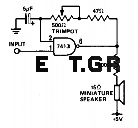
This circuit is useful for monitoring slow logic pulses as a keying monitor or digital clock alarm. The Schmitt trigger is connected as an oscillator. The trimpot controls the pitch of the output. When the input goes high, the...
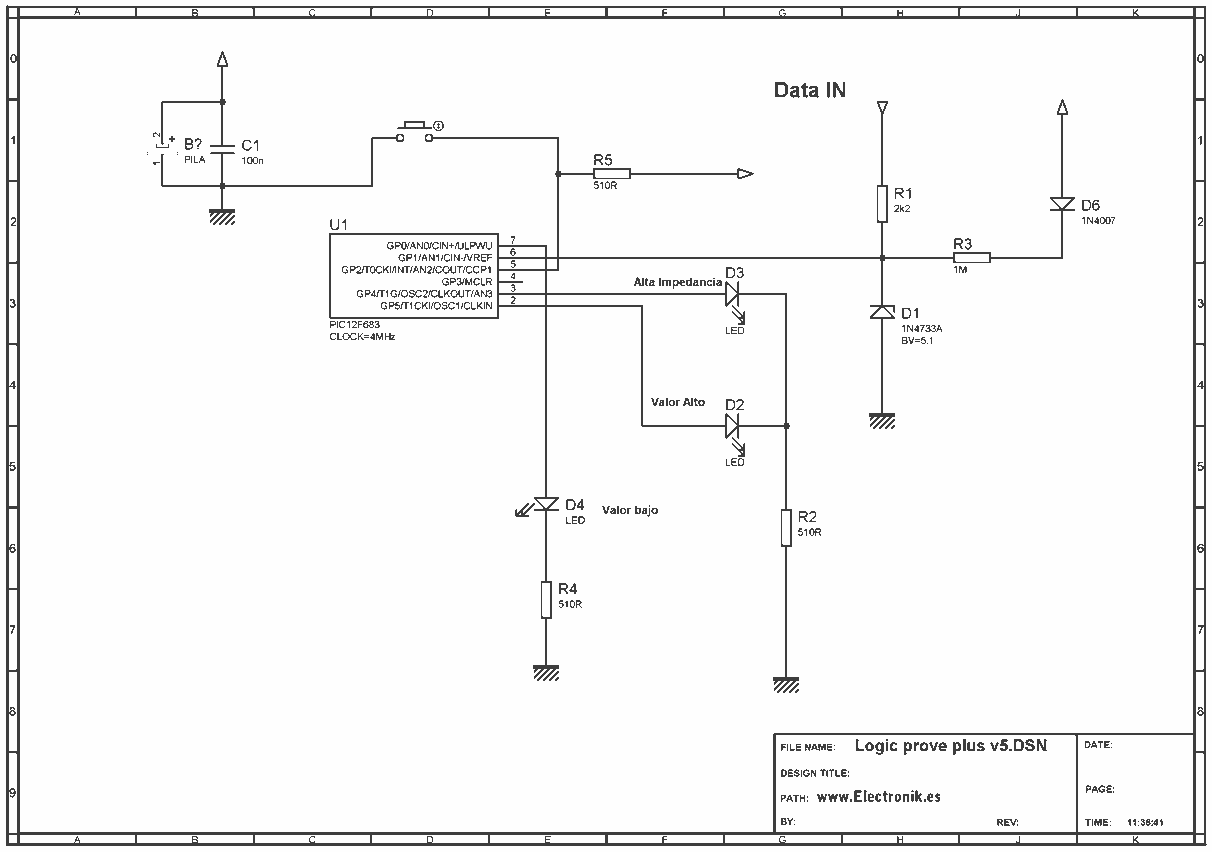
This project is based on a probe logic states, capable of measuring levels from TTL (5v) to state levels of PLC's (24v). For this we have employed the use of the PIC 12F683 microcontroller, which by its nature is...
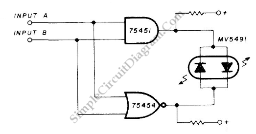
This is a coincidence detector circuit. This circuit is very useful for monitoring complex logic circuits. This circuit has two inputs, A and B. If A and B are... The coincidence detector circuit is designed to identify when two input...

The schematic below illustrates four methods of controlling a relay with a digital logic signal. Figure A can be used in most cases where the relay coil requires 100 mA or less and the input current is 2 milliamps...
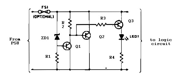
Logic overvoltage protection power supply. Refer to the designated page for an explanation of the power supply circuit diagram mentioned above. The logic overvoltage protection power supply is designed to safeguard sensitive electronic components from voltage spikes that could potentially...
This tester is designed to locate stray electromagnetic (EM) fields. It will easily detect both audio and RF signals up to frequencies of around 100kHz. Note, however that this circuit is NOT a metal detector, but will detect metal...