
I need the most basic circuit diagram for wireless energy transfer please

The inquiry specifically seeks a straightforward wireless energy transfer circuit diagram, ideally simpler than the one previously encountered.
While it is theoretically possible to create a slightly simpler circuit than the one referenced, it is noted that the existing circuit is remarkably simple and serves as an excellent starting point. The critical aspect to consider is that the transmitting and receiving circuits must be tuned to resonate at the same frequency. This tuning requires that the transmit and receive coils be identical, and the 4.7nF capacitors used for tuning must also match. Given that 4.7nF capacitors can vary by approximately +/-10% or more, it may be necessary to add a few hundred picofarads in parallel with one of the two 4.7nF capacitors to achieve optimal matching. However, even without precise matching, the circuit should still function adequately. The voltage requirement is not critical, but a rating of 10 volts or higher is necessary, which is typically met by all 4.7nF capacitors available on the market.
For those beginning in wireless energy transfer, it is advisable to focus on basic components such as inductors, capacitors, and a suitable power source. A typical circuit may consist of a primary coil connected to an alternating current (AC) source, inducing a magnetic field, and a secondary coil positioned within this field to capture the energy. The selection of components should prioritize ease of sourcing and compatibility, ensuring that all parts can be readily obtained from local electronics suppliers or online stores.
In summary, the design of a wireless energy transfer circuit requires careful consideration of the resonant frequency of the coils and capacitors. Beginners should seek out clear, simple schematics and be prepared to experiment with component values to achieve optimal performance in their projects.Instructions to put together a small project on wireless energy transfer. If anyone knows of a good schematic that is super simple and geared towards noobs could you please share, or leave instructions. The simplest one I`ve found so far is this one off of some Hungarian guy`s youtube channel. It`s kinda hard for me to decipher and I when it comes to the capacitors I have no idea where to find these components.
Found a few at the ol` radio shaq but some I can`t find anywhere so I`d like a simpler circuit if there is one. If you know of an even simpler one to get me started with experimenting with w. e. t. please share or point me in the right direction. Thanks! Seriously Okay here goes - "Do you know where I can find a simple wireless energy transfer circuit diagram " Preferably one simpler than this.
Digital Brent Aug 26 `12 at 22:17 @Insilico - his "question" is filled with valid questions. They are to some extent in the "passive voice" which makes them look less like questions. eg when he says "could you please share, or leave instructions" this IS a question and techically he could out a at the edn BUT the answer would be - "Yes" and indeed I COULD do so. But the questions relly menas "I would be grateful if you would:. , . Russell McMahon Aug 27 `12 at 4:15 @RussellMcMahon: I didn`t say that it wasn`t a valid question, in fact I think it`s an interesting problem.
I`m just saying that one should make the question explicit. In silico Aug 27 `12 at 4:29 @Insilico - Our positions appear unlikely to assymptote. By asking ". what`s the question " you ARE "saying" that it isn`t a valid question. Or that you are unable to see a question. You now say that you COULD see questions but that they did not match your required style guides. You can the better pursue that line of march at Stack Exchange English Language & Usage and general pedantry. "Explicit" means "Very specific, clear, or detailed. ". The question set meets those three hurdles well enough, methinks. Russell McMahon Aug 27 `12 at 8:13 While it is theoretically possible to make a very slightly simpler circuit than that one, this circuit approaches being utterly brilliant in its simplicity.
If it works as well as it appears it should then it`s an excellent starting point. The main point to watch is that the transmit and received circuits should be tuned to (or "resonate at") the same frequency. For this to happen the transmit and receive coils need to be the same and the 4. 7nF capacitors which are used to "tune" them should also be matched, As 4. 7 nF caps may vary by say +/-10% or more depending on the type used, it may be necessary to add a few hundred pF in parallel with one or other of the two 4.
7 nF capacitors to get best match. See below. But, even without matching it should work O. Voltage is non critical. 10 Volt or more rating is needed but as all 4. 7n you will find will be rated at more than 10V you do not need to worry about the voltage rating. 🔗 External reference
Related Circuits
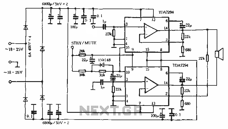
Europe's leading SGS-THOMSON STMicroelectronics recently introduced a new power integrated amplifier, the TDA7294, to the Chinese mainland market. This amplifier, characterized by a cold and hard tone, is particularly suited for Hi-Fi applications such as home theaters and active...
The first BC109C transistor (on the left side) functions as a buffer, offering the circuit a high input impedance of approximately 250k ohms and a voltage gain slightly less than unity. As the Baxandall tone control circuit is a...
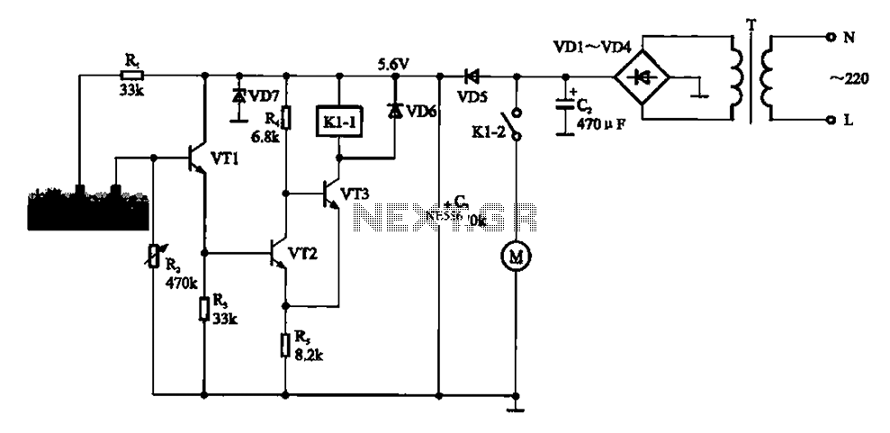
Automatic sprinkler control circuit. This circuit primarily consists of a humidity sensor, a detection signal amplifying circuit (including transistors VT1, VT2, and VT3), a power supply circuit (comprising a filter capacitor C2, a bridge conditioning circuit UR, and a...
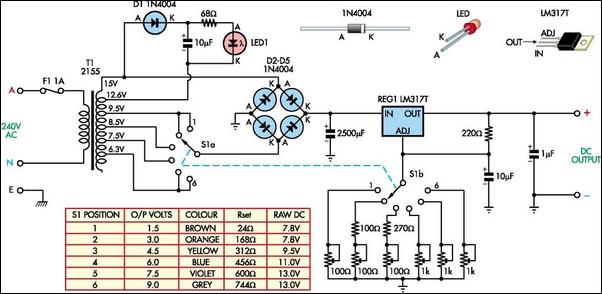
The following circuit illustrates a Battery Replacement Power Supply Circuit Diagram. This circuit is based on the LM317 integrated circuit. Features include the ability to replace... The Battery Replacement Power Supply Circuit utilizes the LM317 voltage regulator to provide a...
Open and short circuit tests on a transformer are conducted to determine the equivalent circuit of the transformer, assess its voltage regulation, and evaluate its efficiency. The open circuit test is performed by applying the rated voltage to the primary...
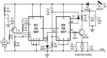
The following circuit illustrates an infrared toy car motor controller. This circuit is based on the 4047 and 4017 integrated circuits (ICs). Features: 16V. The infrared toy car motor controller circuit utilizes two primary integrated circuits, the 4047 and the...