
Make a singing MSP430 microcontroller
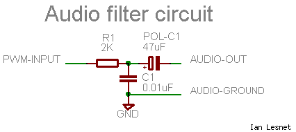
To implement this circuit, the low-pass filter can be constructed using a resistor (R1) and a capacitor (C1) connected in series, with the output taken from the junction between these two components. The resistor value of 2k ohms and the capacitor value of 0.01µF create a cutoff frequency that effectively filters out higher frequency components of the PWM signal while allowing the desired audio frequencies to pass through. The cutoff frequency (fc) can be calculated using the formula fc = 1/(2πRC), where R is the resistance in ohms and C is the capacitance in farads. For the given values, this results in a cutoff frequency suitable for audio applications.
Furthermore, the use of an electrolytic capacitor (POL-C1) in series with the output is crucial for removing any DC offset that may be present in the PWM signal. This ensures that only the AC component of the signal reaches the speaker or amplifier. The recommended range of capacitor values (4.7µF to 47µF) provides flexibility in component selection while maintaining audio fidelity.
In testing, the PWM signal generated by the MSP430 is verified using Test Program 1, which produces a 50% duty cycle signal, resulting in a continuous tone. This setup can be visually demonstrated through a short video clip, illustrating the effectiveness of the low-pass filter and the overall circuit design in producing clear audio output. This circuit design can be applied in various audio applications where PWM signals need to be converted into analog audio signals suitable for amplification and playback.The signal from MSP430 PWM pin isn`t quite ready to drive a speaker or amplifier. First, we can clean up the signal a bit by running it through a low pass filter. This clips the sharp edges from the PWM waveform to make it sound a bit more natural. You can calculate the ideal low pass filter for a given frequency with a calculator like this. I u sed an 8000Hz frequency because I eventually plan to play and record about 8000 samples-per-second with the digital voice recorder. Note that this is just a fraction of the 48000 samples-per-second used by CD players and PCs. At 8000Hz my ideal low-pass filter has a 0. 01uF capacitor (C1) and a2K ohms resistor (R1). Finally, it`s proper form to block any DC voltage from the signal path using an electrolytic capacitor (POL-C1).
The capacitor allows only the AC waveform to pass out of the circuit. A value between 4. 7uF and 47uF seems to work fine. I didn`t notice a difference among the range of values that I tried for the quality of audio produced. This capacitor is usually not necessary, as most amplifiers have a similar capacitor at the audio input connection.
Test program 1 (test1 in the project archive) creates a 50% `on` signal with the PWM. This generates a continuous tone from the speakers. See it in this short video clip. 🔗 External reference
Related Circuits
Security is a prime concern in our day-to-day life. Everyone wants to be as much secure as possible. An access control for doors forms a vital link in a security chain. The Microcontroller based Home Security System can be...
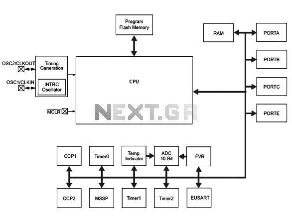
Microchip has announced the availability of new PIC16F1512 and PIC16F151213 XLP microcontrollers. These new XLP (EXtreme Low Power) microcontrollers feature enhanced power management capabilities, making them suitable for battery-operated applications. The PIC16F1512 and PIC16F151213 microcontrollers are designed to operate with...
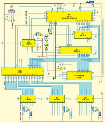
This project is based on the Atmel AT89C52 microcontroller and the Dallas real-time clock (RTC) chip DS12887. It can control and remotely program the switching operations of 24 electrically operated devices, allowing them to be turned on or off...
This article is intended for complete beginners with servo motors. It provides an overview of the basic theory behind servo motors and offers detailed instructions on how to utilize them with AVR microcontrollers such as the ATmega32. Servo motors are...
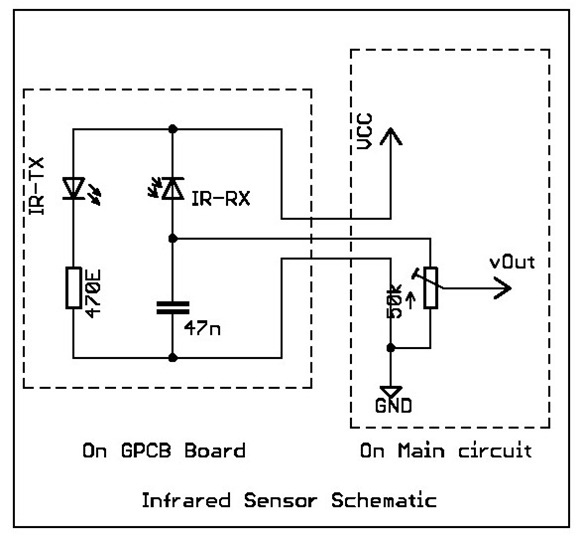
Overview: This tutorial demonstrates the creation of a simple infrared sensor module designed to detect reflecting surfaces. This sensor is capable of identifying reflective materials such as silver or white strips, as well as serving applications in obstacle detection...
An inverter is introduced which primarily utilizes a MOS field-effect transistor in conjunction with a conventional power transformer. The output power of the inverter is determined by the specifications of both the MOS field-effect transistor and the transformer, thereby...