
A digital display clock signal source CD4543 CD4060 CD4518
The digital display clock signal source circuit serves as a critical component in various electronic systems, providing accurate timing signals that can be utilized for synchronization and control purposes. The circuit's architecture typically involves two main types of pulse generators: an automatic pulse generator that continuously produces clock pulses at a predefined frequency, and a manual pulse generator that allows for user-defined pulse generation.
The automatic pulse generator usually employs a stable oscillator circuit, which may consist of a 555 timer or a crystal oscillator, ensuring reliable and consistent clock signals. The output of this generator feeds into a pulse counting mechanism, which counts the number of pulses over a specified time interval. This counting function is essential for applications requiring precise time measurement or event counting.
The manual pulse generator may incorporate switches or buttons that enable the user to initiate pulse generation on demand. This feature is particularly useful in testing scenarios or when specific timing events need to be triggered manually.
The pulse counting components may include flip-flops or counters that register the incoming pulses and convert them into a format suitable for display. The digital display components, often based on LED or LCD technology, present the counted pulses in a human-readable format, allowing users to monitor the timing signals easily.
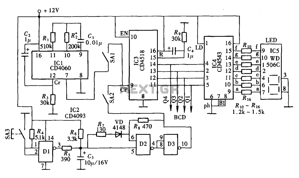
Overall, this digital display clock signal source circuit integrates various electronic elements to create a versatile timing solution, suitable for applications ranging from simple timing tasks to complex control systems.Digital display clock signal source circuit shown in the figure is taken from a multi-point detection control box in the actual circuit. It mainly consists of automatic and man ual pulse generator clock pulse generator, pulse counting and digital display components.
Related Circuits

The B8422 Nixie tubes are intended for use in an alarm clock on a bedside table. The collection of homemade clocks in the house has expanded, with the bedroom remaining unaffected by this clock-making enthusiasm. The B8422 Nixie tubes,...
In some cases, a differential input is needed for voltage measurement. By using a single operational amplifier, it is possible to construct an adapter that provides a floating voltage reference. To achieve a differential input for voltage measurement using an...
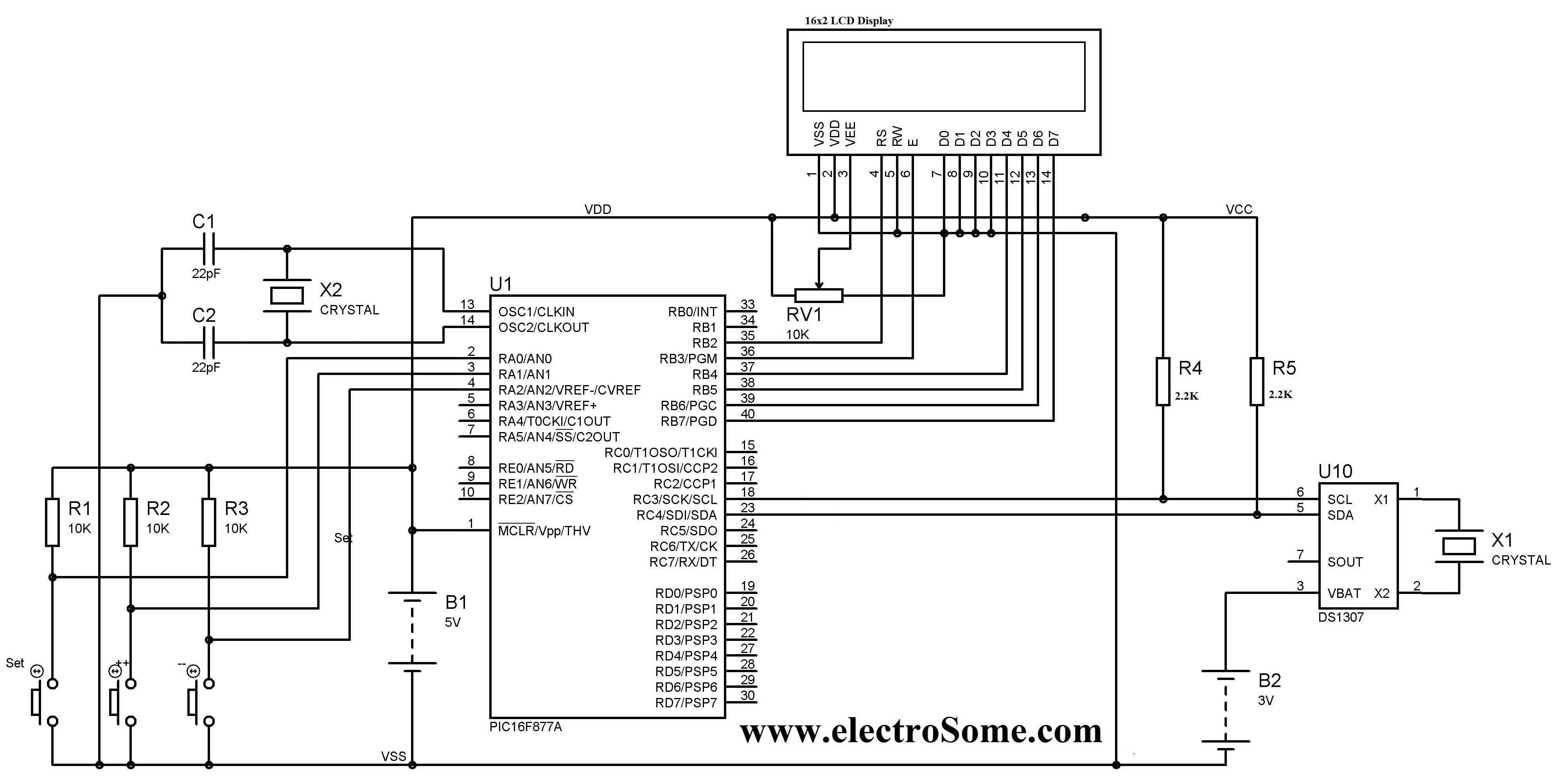
A digital clock can be constructed using a PIC microcontroller, DS1307 real-time clock (RTC), and a 16x2 LCD display. The DS1307 RTC operates in either 24-hour or 12-hour mode with an AM/PM indicator. It adjusts automatically for months with...
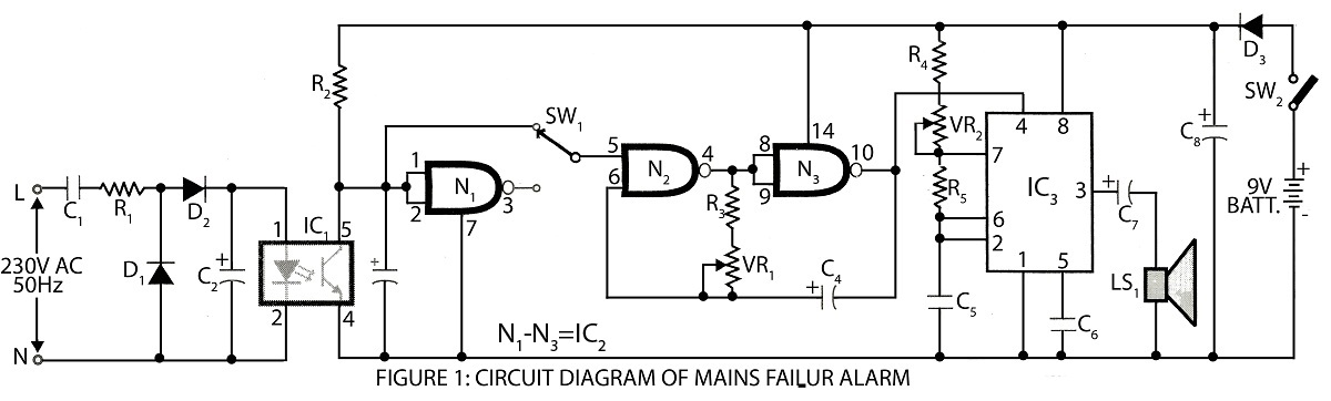
A digital mains failure and resumption alarm circuit utilizes an optocoupler to generate an audible sound. This circuit diagram includes a description of various alarm circuits for digital mains failure. The digital mains failure and resumption alarm circuit is designed...
A clock-controlled relay, also known as a time delay relay, allows for the automatic activation of a load, such as a water pump, at a predetermined time. This device utilizes a standard clock mechanism to trigger the circuit, enabling...
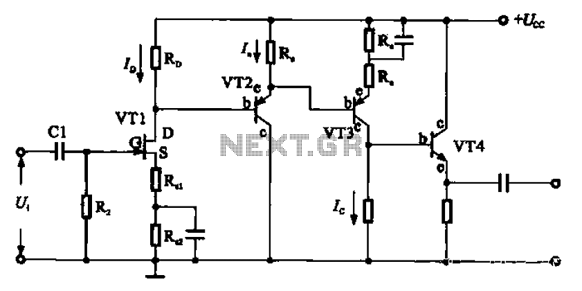
A combination of a common-source grounded emitter amplifier and a common emitter amplifier. The input impedance of the common emitter amplifier is in the range of 1.03 fl. Directly connecting the FET drive can be challenging; however, utilizing an...