
Make Lm324 Op Amp Swing Rail-To-Rail
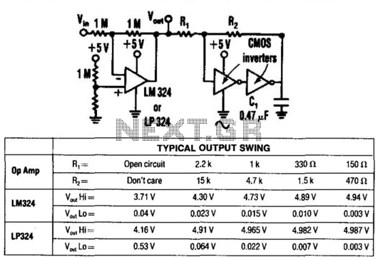
The circuit employs two CMOS inverters configured in series to amplify the output voltage from the LM324 op-amp. The LM324 is a versatile quad op-amp that typically outputs a maximum of 3.5 Vpp when powered by a standard dual supply. The use of CMOS inverters provides a means to boost this output to 4.9 Vpp, which can be beneficial in applications requiring higher voltage levels without significant power consumption.
The recommended load for this configuration is light, specifically under 30 mA, to prevent overloading the inverters, which could lead to distortion or failure. The choice of inverters is flexible, allowing for various models, including the 74C00, 74C02, 74C14, CD4001, and CD4011. These inverters are characterized by their high input impedance and low output impedance, making them suitable for this application.
In the schematic, the output of the LM324 is connected to the input of the first CMOS inverter. The output of this inverter is then fed into the input of the second inverter. The final output is taken from the output of the second inverter, which is now capable of delivering an increased voltage level. The power supply for the inverters should match their specifications, typically a dual supply of ±5V to ±15V, depending on the specific inverter model used.
It is crucial to ensure that the circuit is designed with appropriate bypass capacitors near the power supply pins of the inverters to maintain stability and reduce noise. Additionally, proper layout techniques should be employed to minimize parasitic capacitance and inductance, which can affect the performance of the circuit, especially at higher frequencies. By using two CMOS inverters, the output for an LM324 op amp can be increased from 3.5 Vpp to 4.9 Vpp. This circuit is only recommended for light loads (<30 mA) and for relatively slow op amps. Any CMOS inverter (74COO, 74C02, 74C14, CD4001, CD4011, etc.) can be used. 🔗 External reference
Related Circuits
This is an economical 150 Watt amplifier circuit that utilizes two complementary Darlington power transistors, TIP 142 and TIP 147. It is capable of delivering a robust 150 W RMS to a 4 Ohm speaker, offering significant audio output....
The video amplifier depicted in the diagram is a well-established design that is both simple and effective. However, there is a risk of damaging the transistors if the potentiometers (black level and signal amplitude) are set to their extreme...

The voltage Vc1 increases linearly when the pull-up resistor RA in the monostable circuit is replaced with a constant current source, resulting in the generation of a linear ramp. The figure illustrates the linear ramp generating circuit and the...
A common telecoil follows the MM formula (magnetic-acting) and has an impedance of approximately 600 ohms to effectively receive signals. It is necessary to reduce the impedance in the high-frequency segment, which is achieved by placing a 150pF capacitor...
The push-pull MiniBlok II amplifier utilizes the cost-effective 13EM7 "dissimilar dual triode" (or its variants, the 10EM7 or 13EM7/15EA7), maintaining the same operating point as the original single-ended design for a fair comparison between the two topologies. Two of...
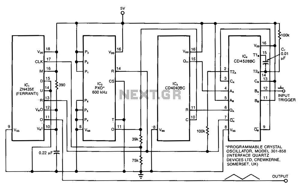
The ramp generator serves as a cost-effective alternative to commercial function generators, offering a more linear and repeatable output compared to traditional analog integrators. This circuit produces a triangle waveform in burst mode, generating two cycles of 10.24 ms...