
555 ic linear ramp sawtooth

In a monostable circuit configuration, the behavior of the output voltage can be significantly influenced by the components used. When the standard pull-up resistor RA is substituted with a constant current source, the voltage across capacitor C1, denoted as Vc1, exhibits a linear increase over time. This is attributed to the constant current flowing through the capacitor, which charges it at a uniform rate, leading to a linear ramp waveform.
The circuit typically employs a PNP transistor to provide the constant current. When the trigger signal is applied, the PNP transistor becomes conductive, allowing a steady current to flow through the resistor and into capacitor C1. The charging process can be described by the relationship I = C * (dVc/dt), where I is the constant current, C is the capacitance, and dVc/dt represents the rate of change of voltage across the capacitor. Since I is constant, the voltage Vc1 increases linearly with time.
The waveform generated by this configuration can be visualized as a straight line when plotted on a graph, with time on the x-axis and voltage on the y-axis. This linear ramp is crucial in various applications, including timing circuits and signal processing, where precise timing and waveform shapes are required.
The resistor in conjunction with the PNP transistor plays a vital role in determining the magnitude of the constant current, which in turn dictates the slope of the ramp. By selecting appropriate values for the resistor and capacitor, designers can tailor the ramp's characteristics to meet the needs of specific applications.
In summary, the integration of a constant current source in place of a pull-up resistor in a monostable circuit allows for the generation of a linear ramp voltage across a capacitor, providing a reliable and predictable output waveform suitable for various electronic applications.The Vc1 increases linearly when the pull-up resistor RA in the mono stable circuit is replaced with constant current source, generating a linear ramp. This is the figure that shown the linear ramp generating circuit and the generated linear ramp waveforms illustration; The current flowing through capacitor C1 becomes a constant current generated b
y PNP transistor and resistor when the trigger starts in a timer configured as shown in figure below. 🔗 External reference
Related Circuits
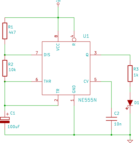
The connection point for the positive terminal of the 9V battery is represented as a circle at the end of a line labeled "+9V." This indicates where to apply power to the circuit. The 0V or "GND" of the...
This is a basic 555 square wave oscillator used to produce a 1 kHz tone from an 8-ohm speaker. In the circuit on the left, the speaker is isolated from the oscillator by an NPN medium power transistor, which...
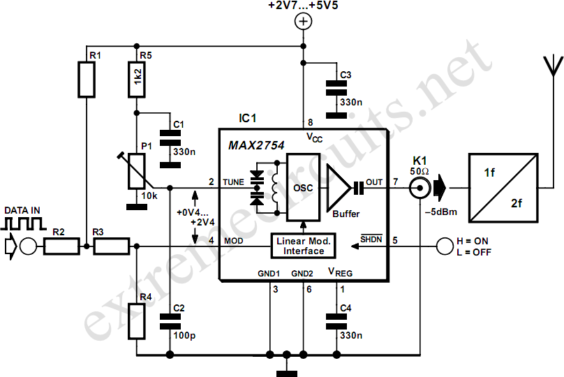
High-frequency voltage-controlled oscillators (VCOs) are challenging to construct. Maxim has developed an integrated 1.2 GHz oscillator, the MAX2754. The center frequency is adjustable via the TUNE input, while a linear modulation input enables frequency modulation. This integrated circuit (IC)...
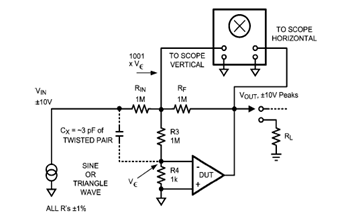
The diagram below illustrates a classic test fixture that has been utilized for an extended period to assist individuals in addressing non-linearity errors. The classic test fixture depicted in the diagram serves as a fundamental tool in electronics testing and...

I will also explain how you can build a 1.5W PA transmitter. The project will include PCB, components and instructions how to make coils, assembly and testing. First let's discuss and learn about the RMS value of a sine...

The remote control circuit consists of two main components: the transmitter and the receiver. A simple schematic diagram illustrates the remote control setup. The transmitter circuit utilizes a NE555 timer IC to generate a specific frequency. The receiver circuit...