
The MiniBlok II Push-Pull Amp
The MiniBlok II amplifier circuit employs a push-pull configuration that enhances audio fidelity and efficiency. The 13EM7 tubes are strategically arranged to leverage their dual triode structure, with one triode functioning as a preamplifier and the other two operating in push-pull mode for output amplification. This design choice allows for a balanced output stage, which is crucial for minimizing distortion and improving sound quality.
The power supply architecture consists of three distinct supplies, each serving a specific purpose. The "A" supply provides filament heating, ensuring that the tubes reach their optimal operating temperature. The "B" supply delivers high voltage to the plate circuits, which is essential for the amplification process. The "C" supply offers negative grid bias, which is critical for controlling the operating point of the output tubes.
The choice of a 24VAC, 40VA Class 2 transformer for the MiniBlok II is significant. This transformer is designed for reliability and efficiency, providing sufficient power for the tube heaters while maintaining a compact size. The series connection of the tube heaters ensures that they operate effectively within their rated specifications, despite the slight undervoltage.
The rectification stage, consisting of diode D4 and capacitors C5, is designed to convert the AC supply to DC efficiently. The resulting voltage is used in conjunction with the cathode resistors to establish a balanced biasing scheme that compensates for any current mismatches between the output tubes. This innovative biasing approach not only enhances performance but also reduces the potential for distortion, making the MiniBlok II a robust choice for audio amplification applications.
Overall, the design of the MiniBlok II amplifier reflects a careful consideration of component selection, circuit topology, and operational efficiency, resulting in a high-quality audio amplifier suitable for various applications.As in the original single-ended design, the push-pull MiniBlok II uses the relatively inexpensive 13EM7 "dissimilar dual triode" (or its variants the 10EM7 or 13EM7/15EA7). Using the same tube with essentially the same operating point makes for a more equitable comparison between the single-ended and push-pull topologies.
However, it should be fairly obvious that two of these are required for the push-pull version. As before, one of the small triode sections is used as our preamplifier. The component values are, in fact, exactly the same. The two power triode sections form our push-pull output stage, again with essentially the same operating point. That leaves one small voltage amplifier triode, which will form our phase-inverter for the "paraphase splitter".
As before, there are essentially three separate power supplies required: The first ("A" supply) is to heat the filament of the tubes, the second provides the high voltage for the plate circuits (the "B" supply), and the third provides a portion of the negative grid bias for the power amplifier ("C" supply). Incoming power from the 120 VAC power line is switched by on-off switch S1, and thence applied to step-down transformer T1.
Unlike the replacement-grade transformer used in MiniBlok, however, MiniBlok II uses a 24VAC, 40VA "Class 2" transformer. This kind of transformer is commonly used to provide low-voltage AC in house wiring, and is supplied with a large mounting nut suitable for installing in standard circuit boxes.
While these are more expensive than the usual run of experimenter transformers, they are of higher quality and therefore capable of supplying more power for a given physical size. Although a 24V, 40VA unit is not much larger than the 12. 6 volt at 2 ampere unit used for T1 in MiniBlok, it is capable of nearly twice the output power. As before, the output from T1 supplies the power for the tubes` heaters. The two tubes` heaters are connected in series, resulting in a bit over 12 volts for each filament. (Though this is about a volt lower than the tubes` ratings, it works just fine. ) Again, we don`t bother converting to DC, in this application an AC heater is just fine because 1) we`re not dealing with extremely high gain, and 2) the 13EM7`s indirectly-heated cathode is naturally highly immune to AC hum.
At the same time, this 24 volt AC supply is connected to the network consisting of diode D4 and capacitors C5. This is a simple half-wave rectifier that provides about 35 volts DC at the junction of D4 and C5. This could have been used as our C supply (grid bias) for the output stages, but we`re going to go an extra step to help insure that our two output tubes are balanced.
Part of our grid bias is derived from cathode resistors R15 and R16. Assuming that the tubes will draw about 40 mA in operation, this means that the voltage across R15 and R16 will be (330 * 0. 035)V = 13. 2 volts. This means that we only need about 15 volts of additional grid bias to set the tubes near our desired operating point.
The network consisting of resistor R14 and zener diode D3 provides this grid bias voltage. During operation, mismatches between the two output tube sections will be significantly reduced by this combination biasing method. The reason is that if one of the tubes should draw more current, it will cause a higher voltage drop across the cathode resistor; this in turn increases the grid-to-cathode voltage, tending to buck the increase in current.
In the prototype, there was a 50% difference in plate current between the two tubes I had on hand, using fixed-bias only; this dropped to a mere 10% difference using the joint cathode-grid biasing scheme. At the same time, it only "wastes" half of the supply voltage drop that a straight cathode biasing scheme would require.
An optional pilot lamp network cons 🔗 External reference
Related Circuits
This is a very simple, low cost, Hi-Fi quality power amplifier. You can build it 5 ways, like its shown in the table (from 20 W to 80 W RMS). The first thing that you must do, is to...
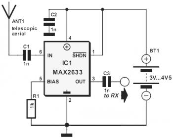
This diagram represents a VHF RF preamplifier circuit operating within the frequency range of 100-175 MHz using a single MAX2633 chip. The circuit is suitable for the entire VHF broadcast and PMR band (100-175 MHz) and can be constructed...
The circuit diagram of a guitar preamplifier is designed to accept any standard guitar pickup and features two signal outputs. A typical example of a pickup attached to a guitar headstock is illustrated. The pickup device consists of a...
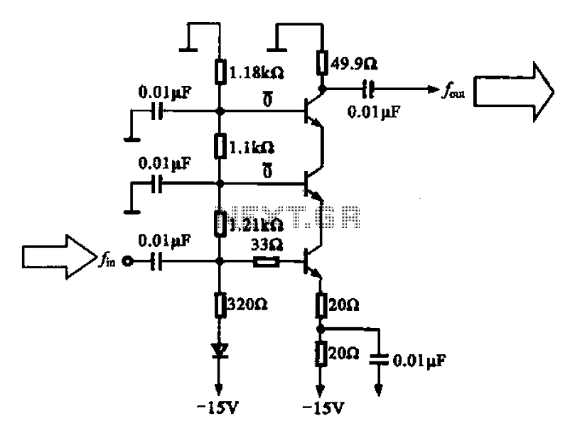
A back radiation small buffer amplifier is presented, featuring an inverse radiation small buffer amplifier configuration. The circuit is composed of three transistors connected in series, functioning as a buffer amplifier. This design can be utilized in output amplifiers...
A diode and capacitor can be utilized to clamp an AC signal, shifting the level into the positive region for all cycles. This condition is sometimes necessary to ensure a positive output. In an electronic circuit, clamping is a technique...
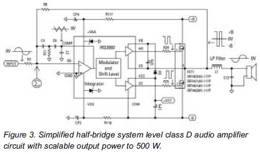
Class D audio amplifiers are now prepared to replace Class AB amplifiers. An integrated high-voltage audio driver simplifies the design and construction of high-power audio systems. Class D audio amplifiers, also known as switching amplifiers, utilize pulse-width modulation (PWM) to...