
make tv transmitter

The main problem a video enthusiast has in obtaining a TV transmitter is that a commercial units are expensive. However, we have some good news! You can build the TV Transmitter described here for less than $30 in one evening! The easiest way to do that is to order the kit thats available from the source given in the Parts List (a custom case for the kit is also available).
Nevertheless, we present enough information here to build the TV Transmitter from scratch. The TV Transmitter combines line- level audio and video signals, and transmits the resulting signal up to 300 feet. The circuit can be powered from a 9- volt battery. It is suggested that a 12-volt DC supply during be used during the alignment procedure. This would insure maximum transmission range and best possible picture. Aligning the TV Transmitter requires no special equipment whatsoever, and it is a very simple procedure.
The Transmitter`s output can be tuned to be received on any TV channel from 2 to 6. The range of channels is wide enough so that the unit will not interfere with other TV viewers who are nearby. To comply with FCC rules, it is mandatory the nearby TV viewers are not disturbed by the transmission.
If your activities interfere with the reception from a licensed station, regardless of the reason, you must shut down your unit. Figure 1 is the schematic diagram of the TV Transmitter circuit. Video signals input at jack J1 are first terminated by resistor R6 and coupled through capacitor C1 to clamping-diode D1.
The clamping forces the sync pulses to a fixed DC level to reduce blooming effects. Potentiometer R3 is used to set the gain of the video signal; its effect is similar to that of the contrast control on a TV set. Bias-control R7 can be used to adjust the black level of the picture so that some level of signal is transmitted, even for a totally dark picture.
That way, a TV receiver can maintain proper sync. As we`ll get to later, potentiometers R3 and R7 are cross adjusted for the best all-around performance. RF-transformer T1 and its internal capacitor form the tank circuit of a Hartley oscillator that`s tuned to 4.
5 megahertz. Audio signals input at J2 are coupled to the base of Q3 via C2 and R4: the audio signal modulates the base signal of Q3 to form an audio subcarrier thats 4. 5-megahertz higher than the video-carrier frequency. The FM modulated subcarrier is applied to the modulator section through C5 and R9. Resistor R9 adjusts the level of the subcarrier with respect to the video signal. Transistors Q1 and Q2 amplitude modulate the video and audio signals onto an RF-carrier signal. The operating frequency is set by coil L4, which is 3. 5 turns of 24- gauge enameled wire on a form containing a standard ferrite slug. That coil is part of a Colpitts tank circuit also containing C7 and C9. The tank circuit forms Q4`s feedback network, so Q4 oscillates at the set frequency The RF output from the oscillator section is amplified by Q5 and Q6, whose supply voltage comes from the modulator section.
Antenna matching and low-pass filtering is performed by C12, C13, and L1. Resistor R12 is optional; it is added to help match the output signal to any kind of antenna. (More on that in a moment. ) 🔗 External reference
Related Circuits
Here is a very simple, inexpensive and interesting project which provides lot of fun to a home experimenter or hobbyist. This simple transmitter can transmit speeches or songs within a short range. The circuit uses only one transistor. The...

The device utilizes the USB boot HID keyboard protocol. When connected, it can detect changes in the keyboard LED states (caps lock, num lock, scroll lock), which the firmware uses to initiate new password generation (indicated by four LED...
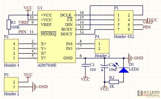
The touch control screen is a common feature in modern electronic products, typically incorporating a colored liquid crystal display (LCD) with a touch-sensitive interface. This technology is user-friendly and effectively replaces traditional fixed keypads. This document introduces the driving...
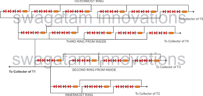
The following article outlines a sophisticated LED sequencing and diverging ring light that can serve as a tail brake light in vehicles. This circuit concept was proposed by a dedicated reader, Mr. Bobby. The design aims to create a...
Construct a low-power FM transmitter using surface-mount devices (SMD) that can be received by a standard FM radio. Soldering surface-mounted devices is relatively straightforward. Many small FM transmitter designs exist, but they often have issues. Firstly, an audio amplifier...

The schematic for this project is deceptively simple compared to the complexity of the circuit's operation. The two signals generated are mixed together at the base of transistor T2, and once it exits the collector of the transistor, the...