
make yourself this low cost rfid access control circuit at home
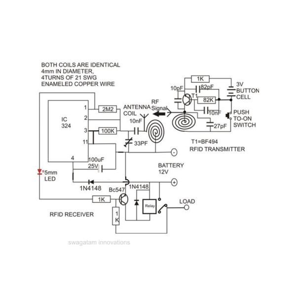
The RFID access control circuit typically consists of several key components: an RFID reader, RFID tags, a microcontroller, and a relay module. The RFID reader is responsible for detecting the RFID tags, which contain unique identifiers. Upon scanning an authorized tag, the reader sends a signal to the microcontroller, which processes the data and determines whether access should be granted or denied.
The microcontroller serves as the brain of the circuit, executing the programmed logic to compare the scanned tag's ID against a database of authorized IDs. If a match is found, the microcontroller activates the relay module, which can control an electronic lock or gate mechanism, allowing access. Conversely, if the tag is unauthorized, the relay remains inactive, preventing entry.
Power supply considerations are also crucial; the circuit typically requires a stable power source to ensure reliable operation. Additionally, incorporating status LEDs can provide visual feedback, indicating whether access has been granted or denied.
For enhanced security, the circuit can be expanded with features such as an alarm system or a logging mechanism to track access attempts. Overall, the RFID access control circuit stands as an efficient and cost-effective solution for managing access control in various applications.Building a RFID access control circuit at home and seeing it actually work can be truly an amazing experience. Although the circuit is not a hi-tech one, but comparing its low cost with the fairly good results obtained simply proves its high degree of efficiency..
🔗 External reference
Related Circuits
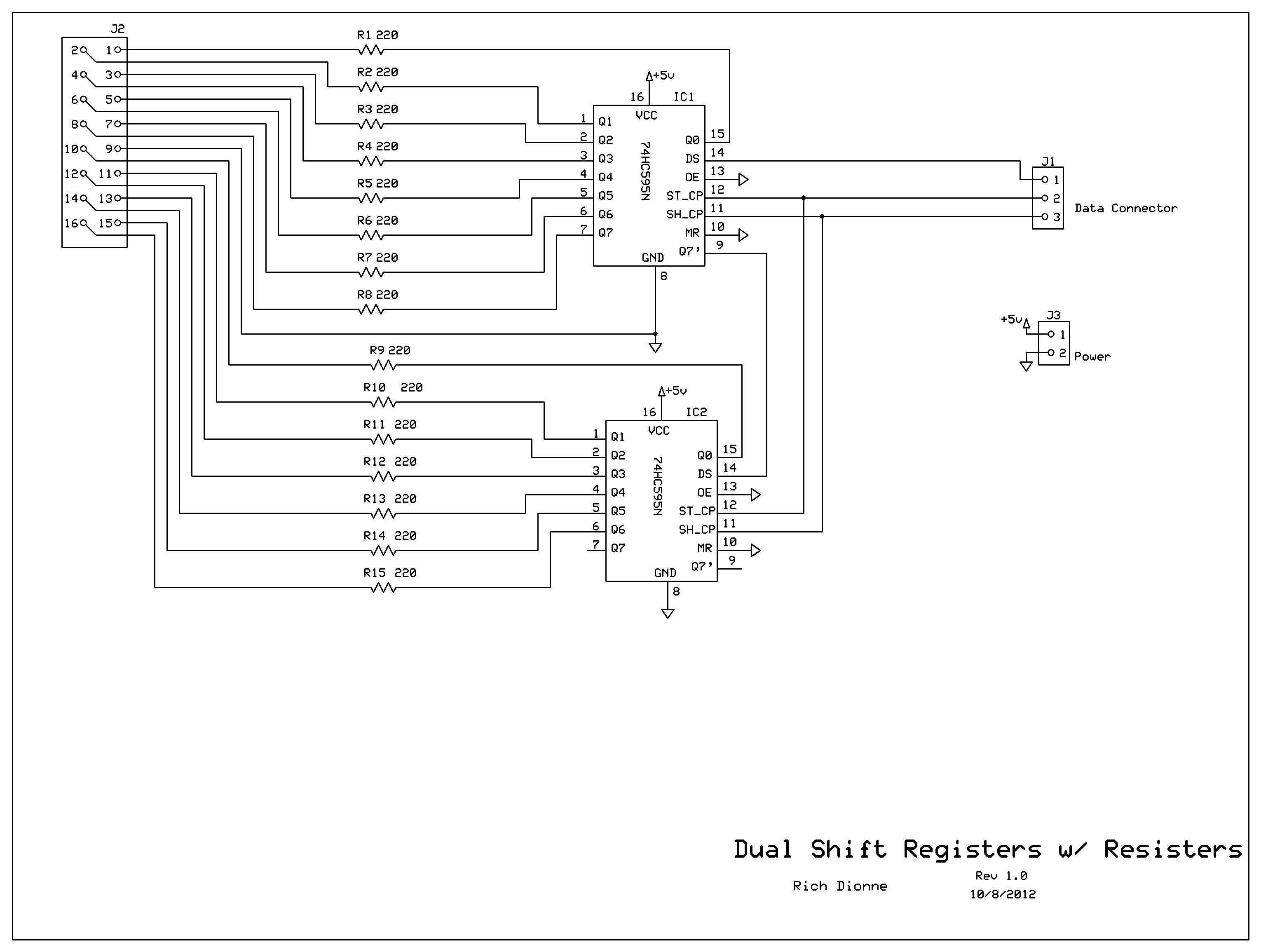
Control the two digits representing minutes; this circuit includes two shift registers, 30 resistors, and 30 LEDs. The schematic illustrates the design. As the circuit design neared completion, it became evident that soldering all components onto a basic prototyping...
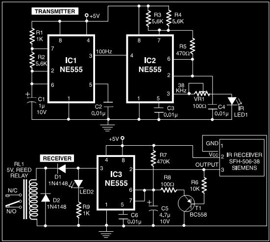
This post discusses a proximity detector circuit primarily utilizing the NE555 integrated circuit (IC). The circuit is designed for burglar alarms based on beam interruption, with the advantage that the transmitter and receiver are contained within the same enclosure,...
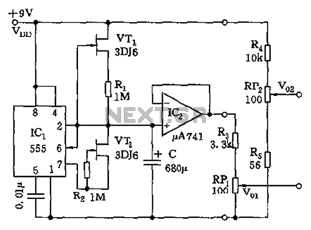
The circuit depicted in the figure is a generator that includes an oscillator, a voltage follower, a zero amplitude adjustment, and a zero shift circuit. It is utilized as a self-balancing recorder for testing signals. The output signal ranges...
This low-cost project allows audio reproduction from a TV without disturbing others. It eliminates the need for wired connections between the TV and loudspeakers by utilizing invisible infrared light to transmit audio signals. Without the use of lenses, a...
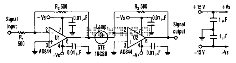
Designers can construct a 15-dB compressor using a miniature lamp and a current-feedback amplifier. The circuit exhibits extremely low distortion at frequencies above the lamp's thermal time constant, indicating that distortion remains negligible from audio frequencies to over 10...
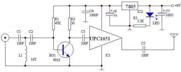
The UPC1651 FM monolithic circuit can be utilized to design a simple, low-cost FM transmitter electronic project. This circuit is specifically designed as a wideband amplifier that covers the HF band through the UHF band. Audio signals from the...
Warning: include(partials/cookie-banner.php): Failed to open stream: Permission denied in /var/www/html/nextgr/view-circuit.php on line 713
Warning: include(): Failed opening 'partials/cookie-banner.php' for inclusion (include_path='.:/usr/share/php') in /var/www/html/nextgr/view-circuit.php on line 713