
upc1651 fm transmitter circuit

The UPC1651 FM transmitter circuit is a versatile tool for creating low-cost FM transmission systems. The circuit operates by amplifying audio signals from a microphone, which are then modulated onto a carrier wave. The microphone captures sound, converting it into an electrical signal that is filtered through capacitor C1 to eliminate high-frequency noise. This ensures that only the desired audio frequencies are processed by the UPC1651 IC.
At the output pin of the IC, the modulated FM signal is generated. The LC circuit composed of inductor L1 and capacitor C3 is crucial for oscillation. The inductor L1 is constructed with 5 turns of 0.5 mm diameter copper wire, wound to a diameter of 4 mm. This design provides the necessary inductance for the circuit's operation. The resonant frequency of the LC circuit can be fine-tuned by adjusting capacitor C3, allowing for flexibility in the transmitter's operating frequency.
The circuit's simplicity and cost-effectiveness make it an ideal choice for hobbyists and educational projects. It is important to ensure that the components are properly selected and assembled to achieve optimal performance. Additionally, considerations regarding the power supply and antenna design will further enhance the effectiveness of the transmitter. Overall, the UPC1651 FM transmitter circuit exemplifies a straightforward yet effective approach to FM broadcasting.Using the UPC1651 FM monolithic circuit can be designed a very simple low cost FM transmitter electronic project. This UPC1651 FM transmitter circuit is specially designed as a wide band amplifier covering the HF band trough UHF band.
Audio signal from the microphone are fed to the input pin of the IC via capacitor C1. C1 acts as a noise filter. The modulated FM signal will be available at the output pin of the IC. Inductor L1 and capacitor C3 forms the necessary LC circuit for creating the oscillations. L1 coil has 5 turns of 0. 5 mm copper wire with 4 mm coil diameter. Adjusting the C3 capacitor will vary the frequency of the transmitter. 🔗 External reference
Related Circuits
Join the forum discussion on this post. This is a simple home telephone ringtone generator circuit built using only a few electronic components. It generates a simulated telephone ringtone and requires only a DC supply. The home telephone ringtone generator...
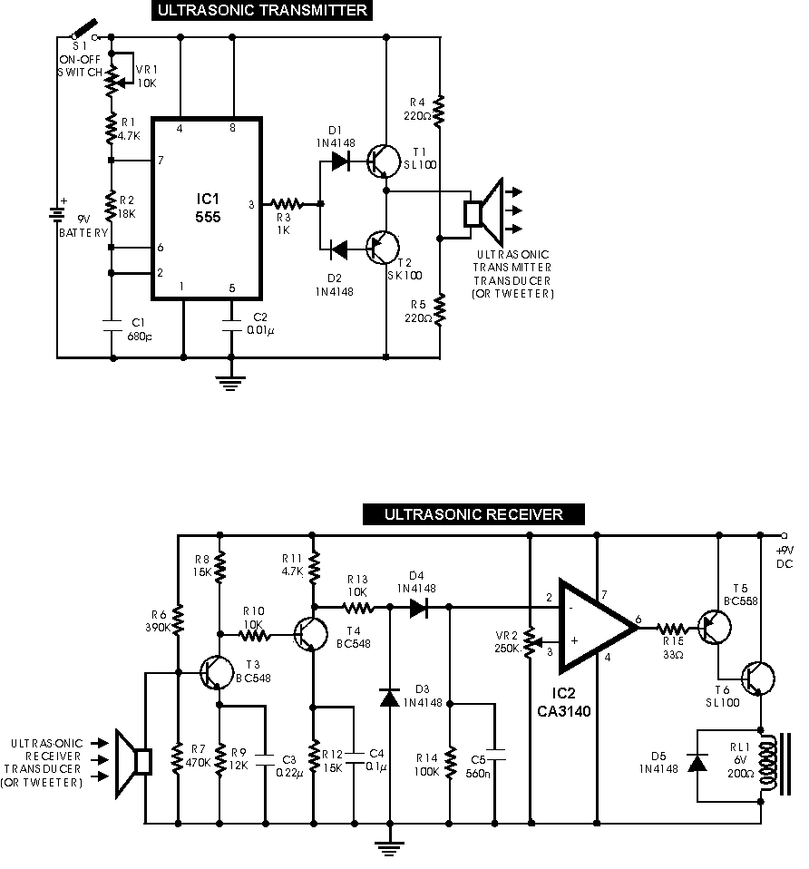
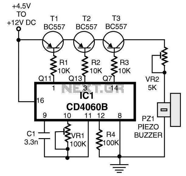
This circuit functions with inaudible (ultrasonic) sound. Sound of frequency up to 20 kHz is audible to human beings. The sound of frequency above 20 kHz is called ultrasonic sound. The circuit described generates (transmits) ultrasonic sound of frequency...
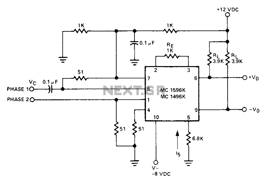
The circuit involves a Signetic balance modem connection utilizing a transistor array as a phase detector. It provides information about the cosine of the phase angle, which corresponds to the frequency of the input signal combined with the integrated...
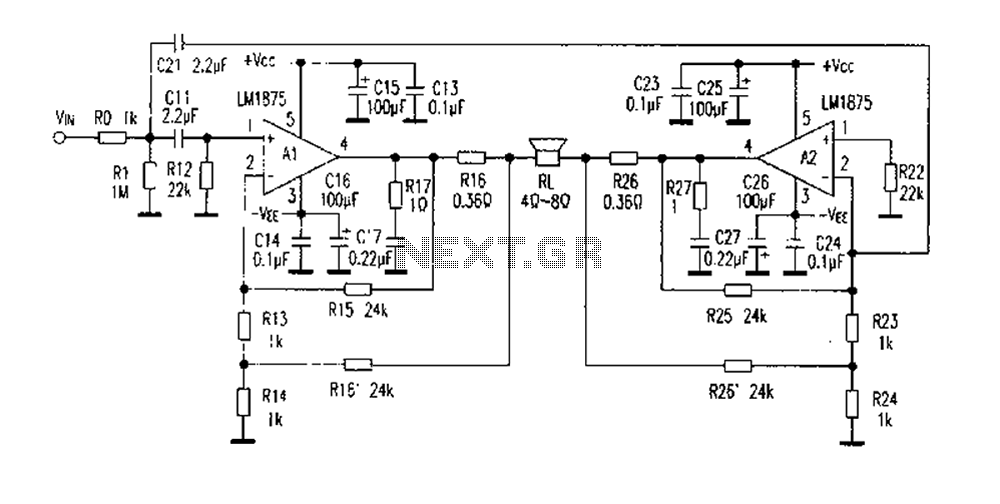
The DC current negative feedback BTL circuit illustrated in Figure 2 eliminates the standard BTL circuit capacitors C12 and C22, which affects the DC characteristics of the circuit. Resistors R16 and R26 function as sampling resistors, while R15, R16,...

This design circuit is a tachometer circuit based on the LM2907 integrated circuit, which can provide zero-crossing data to a digital system. At each zero crossing of the input signal, the charge pump alters the state of capacitor C1...
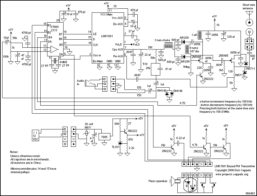
An LMX1601 Phase locked loop, a discreet FET VCO, and an AVR microcontroller combine to make a stable, easy to use monophonic FM transmitter that includes an audio activated switch that turns the transmitter on only when it is...