
Making Differential Probes
To address the limitations of standard multimeters in measuring high current levels, a custom shunt resistor can be designed. A shunt resistor is a precise resistor placed in series with the load, allowing the current flowing through it to generate a voltage drop that can be measured by the multimeter.
To create a suitable shunt for measuring higher currents, the following specifications should be considered:
1. **Shunt Resistor Value**: The resistance value should be chosen based on the maximum current expected in the application. For instance, a shunt resistor of 0.01 ohms would allow for a maximum current of 10 amps to produce a 100 mV drop across it, which is within the measurement range of most multimeters.
2. **Power Rating**: The power rating of the shunt resistor must be sufficient to handle the heat generated by the current passing through it. The power can be calculated using the formula P = I²R, where P is the power in watts, I is the current in amperes, and R is the resistance in ohms. For example, a 0.01-ohm shunt carrying 10 amps would need to dissipate 1 watt of power.
3. **Connection Configuration**: The shunt should be connected in series with the load. Care must be taken to ensure that the multimeter is connected across the shunt resistor to measure the voltage drop accurately.
4. **Calibration**: It is important to calibrate the multimeter with the shunt resistor to ensure accurate readings. This can be done by measuring known currents and adjusting the multimeter readings accordingly.
5. **Safety Considerations**: When working with high voltages and currents, appropriate safety measures should be taken to prevent electrical shock or damage to the multimeter. This includes using insulated tools and ensuring that the circuit is powered off when making connections.
The implementation of a custom shunt resistor allows for an economical solution to measure high currents in DC powered projects, providing both accuracy and cost-effectiveness.Using a modern multimeter to measure current can sometimes be difficult. Many of these meters will only measure up to one amp. However, may 112-volt DC powered projects draw a lot more than that. If you have ever thought of purchasing a commercial shunt to solve the problem, your know just how expensive they can be. Commercial shunts, while very precise, frequently cost more than the projects they are measuring! 🔗 External reference
Related Circuits
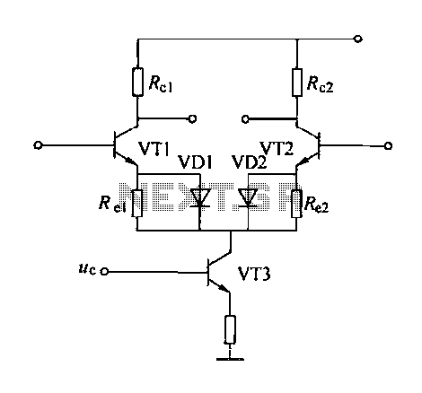
A controllable gain amplifier functions as an automatic gain control circuit within the execution unit. The primary methods for controlling the amplifier's gain involve two approaches: one is by adjusting certain parameters of the amplifier itself, such as emitter...
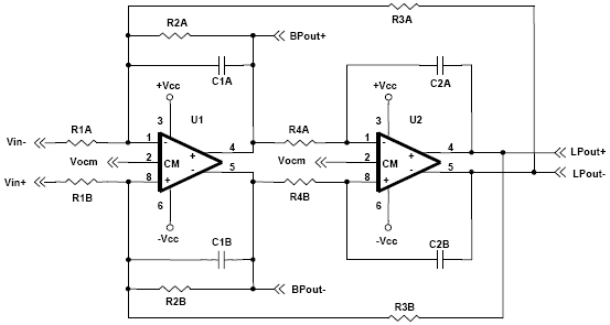
A biquad filter is a type of linear filter that implements a transfer function which is the ratio of two quadratic functions. It is available in low pass, high pass, band pass, and notch configurations. A biquad filter is characterized...
The differential outputs are balanced and designed to drive long lengths of coaxial cable, stripline, or twisted pair transmission lines with characteristic impedances ranging from 50 ohms to 500 ohms. Differential transmission is superior to single-wire transmission as it...
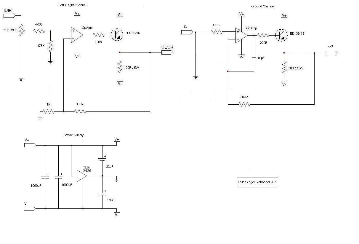
The schematic shows R4 at the emitter of the transistor, as suggested by Amb and Majkel. It should be positioned between the operational amplifier and the transistor, which is also the correct configuration in the CanAmp. The amplifier observed...
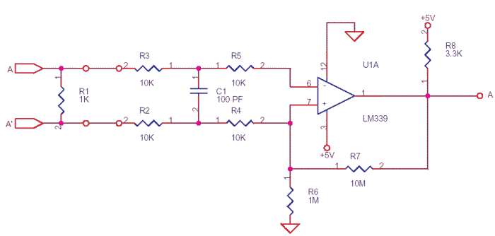
In some cases, a differential input is needed for voltage measurement. By using a single operational amplifier, it is possible to construct an adapter that provides a floating voltage reference. To achieve a differential input for voltage measurement using an...
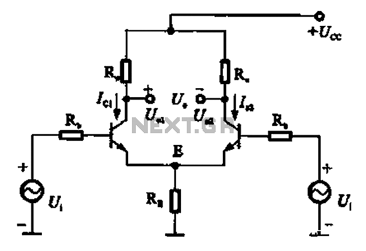
The common mode signal of an emitter-coupled differential amplifier circuit assumes that two equal small increases of the same polarity signal, referred to as the common mode signal, occur simultaneously. This results in an increase in the potential at...
Warning: include(partials/cookie-banner.php): Failed to open stream: Permission denied in /var/www/html/nextgr/view-circuit.php on line 713
Warning: include(): Failed opening 'partials/cookie-banner.php' for inclusion (include_path='.:/usr/share/php') in /var/www/html/nextgr/view-circuit.php on line 713