
differential to ttl convertor
The described system utilizes differential signaling to enhance transmission quality over various cable types, ensuring minimal signal degradation over long distances. The balanced differential outputs are crucial for maintaining signal integrity, particularly in environments susceptible to electromagnetic interference (EMI). By employing differential transmission, the circuit effectively cancels out noise that may be induced along the transmission line, thus preserving the clarity of the transmitted signal.
In practical applications, when the signal voltage diminishes below acceptable levels at the receiving end, a signal amplification circuit can be implemented. This circuit typically comprises an operational amplifier (op-amp) configured in a non-inverting or inverting mode, depending on the desired gain characteristics. The op-amp should be selected based on its bandwidth and slew rate to ensure it can handle the frequency of the input signal without distortion.
Additionally, feedback resistors can be utilized to set the gain of the amplifier, allowing for precise control over the output signal levels. It is advisable to keep the impedance matching in mind, especially when interfacing with 50-ohm to 500-ohm transmission lines, to prevent reflections that could further degrade the signal quality.
Power supply considerations for the op-amp circuit are also essential; a dual power supply may be used to accommodate the positive and negative voltage swings of the differential signal. Proper decoupling capacitors should be included to filter out any noise from the power supply lines, ensuring stable operation of the amplifier.
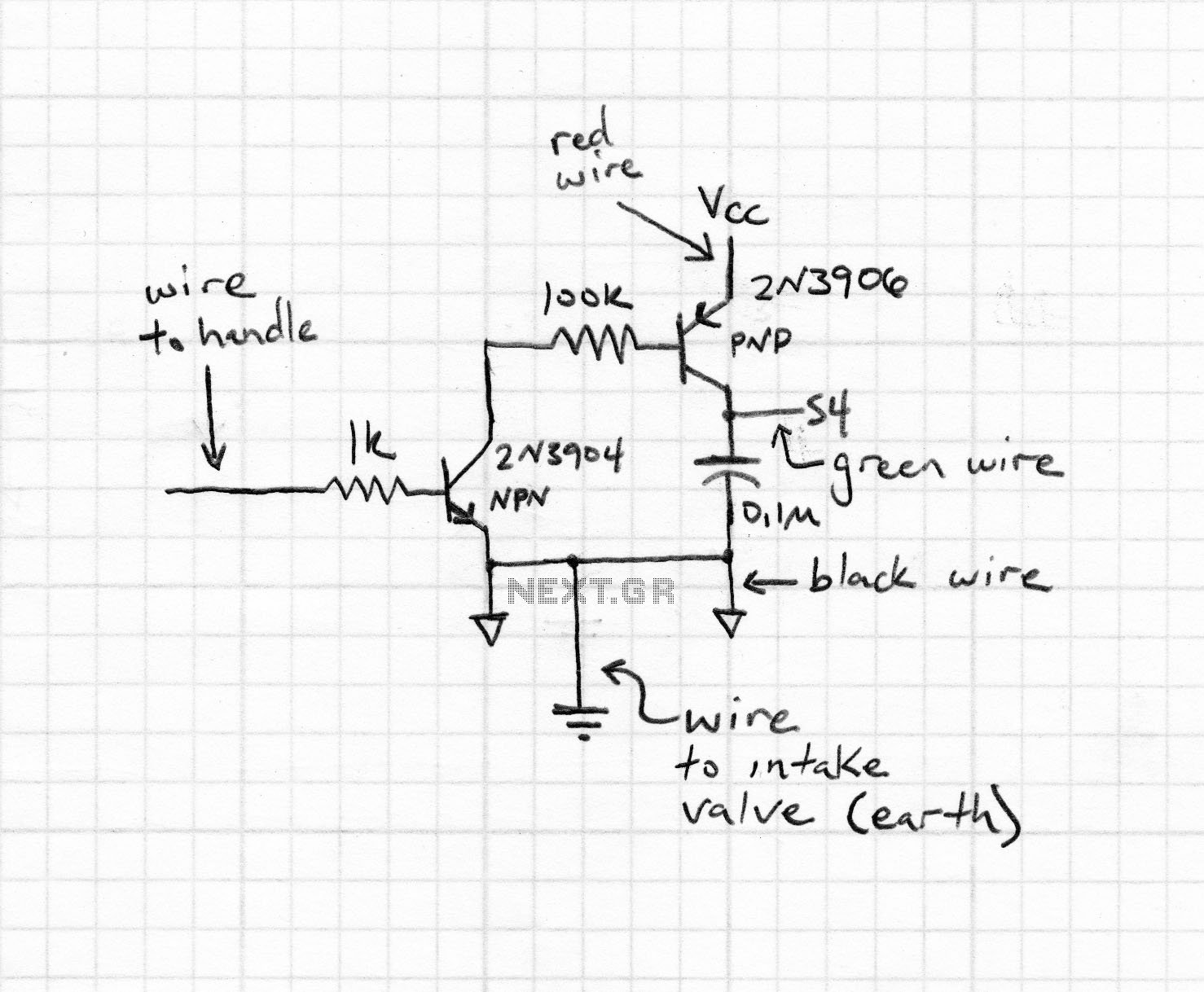
Overall, the integration of a boosting circuit at the receiving end enhances the reliability of differential transmission, making it suitable for applications in telecommunications, data communication, and other fields where signal integrity is paramount.The differential outputs are balanced and are designed to drive long lengths of coaxial cable, strip line, or twisted pair transmission lines with characteristic impedances of 50 ohms to 500 ohms. Differential transmission is superior to single wire transmission in that it nullifies the effects of ground shifts and noise signals which appear as co
mmon mode voltages on the transmission line. If the signal voltage at the end of the line is found to be of insufficient magnitude then the following circuit may be used (at the recipient equipment end) to boost the levels. 🔗 External reference
Related Circuits
In the circuit shown below, if the voltage at the output terminals rises above 6.2V, zener conducts charging capacitor C4. This voltage will fire the silicon-controlled rectifier (SCR), which quickly shorts across the supply rails blowing the fuse. The...

The modification of the differential circuit is illustrated. In Figure A1, an integrator is depicted, and the output is presented. The circuit modification involves integrating the differential circuit with an integrator component, which plays a crucial role in signal processing...
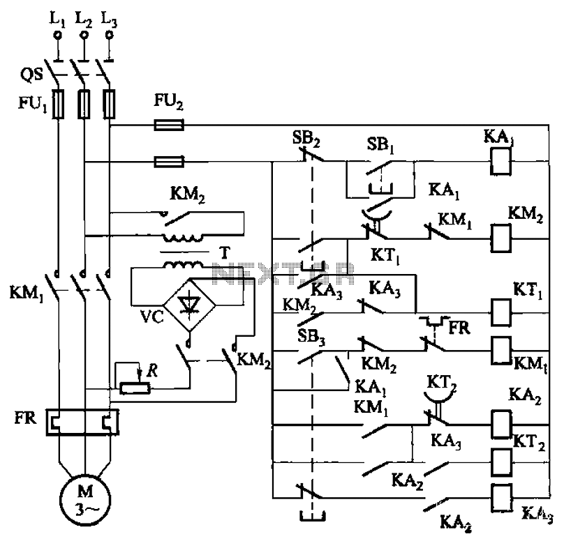
The circuit depicted in Figure 3-143 demonstrates a braking mechanism for a motor that operates effectively during normal shutdown and jog operations. The circuit includes several components, such as the start button (SBz), stop button (SBz), and jog button...
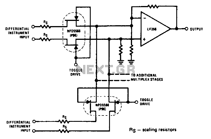
The NPD5566 monolithic dual is utilized in differential multiplex applications where the Rds(ON) should be closely matched. The monolithic dual tracks at better than ±1% over a wide temperature range of -25°C to +125°C, making it an unusual yet...
The circuit measures distances using a modulated laser. It features a fixed voltage regulator (7805) that provides a stable +5 V source, followed by an LM317 adjustable voltage regulator to supply exactly 3 V to the diode laser module,...

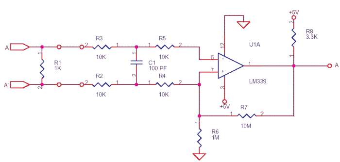
The circuit is designed to convert sinusoidal input signals into TTL output signals and can process input voltages exceeding 100 mV. This circuit typically employs a comparator to achieve the conversion from sinusoidal to TTL levels. The sinusoidal input signal...
Warning: include(partials/cookie-banner.php): Failed to open stream: Permission denied in /var/www/html/nextgr/view-circuit.php on line 713
Warning: include(): Failed opening 'partials/cookie-banner.php' for inclusion (include_path='.:/usr/share/php') in /var/www/html/nextgr/view-circuit.php on line 713