
Electret Condenser Microphone (ECM) Preamplifier
The microphone amplifier circuit is structured around two transistor stages, Q1 and Q2, which provide amplification with minimal noise interference. The configuration of Q1 as a low collector current amplifier is critical for achieving high fidelity in sound reproduction, as it minimizes thermal noise and enhances the signal-to-noise ratio. The 100µF capacitor connected to the emitter of Q1 serves to decouple the emitter resistor, allowing for maximum gain without introducing additional noise.
In the second stage, Q2's direct coupling to Q1 is a significant design choice that eliminates phase shifts, ensuring that the amplifier maintains a consistent frequency response across a broad spectrum. This is particularly important for audio applications where clarity and fidelity are paramount. The feedback mechanism from the emitter of Q2 to the base of Q1 stabilizes the bias point, which is essential for maintaining performance consistency despite temperature variations.
The overall gain of the preamplifier, quantified at around 20dB, indicates that the circuit can effectively amplify weak signals from microphones, making it suitable for various applications, including live sound reinforcement and recording. The low output impedance of the amplifier enhances its ability to drive long cable runs without significant signal degradation, an essential feature for professional audio setups where distance between the microphone and processing equipment can be substantial.
In conclusion, this microphone amplifier design is robust, versatile, and capable of delivering high-quality audio signals under varying conditions, making it an excellent choice for both amateur and professional audio applications.A microphone amplifier that may be used with either Electret Condenser Microphone (ECM) inserts or dynamic inserts, made with discrete components. The preamplifier circuit is self stabilizing and will set its quiescent point at roughly half the supply voltage at the emitter of Q2.
This allows maximum output voltage swing and also the highest dynam ic range. Both transistors should be low noise types. In the original circuit, I used BC650C which is an ultra low noise device. These transistors are now hard to find but BC549C or BC109C are a good replacement. The electret condenser microphone (ECM) contains a very sensitive microphone element and an internal FET preamp, a power supply in the range 2 to 10 volts DC is therefore necessary. Suitable ECM`s may be obtained from Maplin Electronics. Although the schematic is drawn showing a three terminal ECM, two terminal ECM`s may be used, the following page in the practical section shows the changes.
The 1k resistor limits the current to the mic. This resistor should be increased to 2k2 if a supply voltage above 12 Volts DC is used and is not needed if the Mic insert is dynamic. The first stage amplifier built around Q1 is run at a very low collector current. This factor contributes to a very high overall signal to noise ratio and low overall noise output. The emitter resistor of Q1 is decoupled by the 100u realizing a maximum gain for this stage. The noise response of the amplifier measured across the 10k load is shown below. Please note that this plot was made with the mic insert replaced by a signal generator. The second stage amplifier, built around Q2 is direct coupled, this minimizes phase shift effects (introduced with capacitive and inductive coupling methods) and acheives a flat output response from 20Hz to over 100kHz.
The frequency response measured across a 10k load resistor is plotted below simulated using a 12V power source. The emitter voltage of Q2 is also fed back to the base of Q1 via resistive coupling. This also ensures bias stabilization againt temperature effects. Q2 operates in emitter follower mode, the voltage gain of this stage is less than unity, however, the overall voltage gain of the preamplifier is about 100x or 20dB as shown in the bode plot above.
The output impedance is very low and well suited to driving cables over distances up to 50 meters. Screened cable therefore is not necessary. This preamplifier has excellent dynamic range and can cope with anything from a whisper to a loud shout, however care should be taken to make sure that the auxiliary equipment i. e. amplifier or tape deck does not overload. 🔗 External reference
Related Circuits
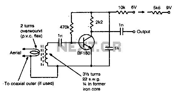
This simple circuit provides a gain of 15 dB and can be mounted on a 1 inch by 2 inch PCB. Coil specifications are provided for a frequency range of 85 to 95 MHz. For other frequencies, the coil...
To complement the 60 Watt MOSFET audio amplifier, a high-quality preamplifier design was necessary. A discrete components topology using +24V and -24V supply rails was chosen, minimizing the transistor count while still achieving low noise, very low distortion, and...
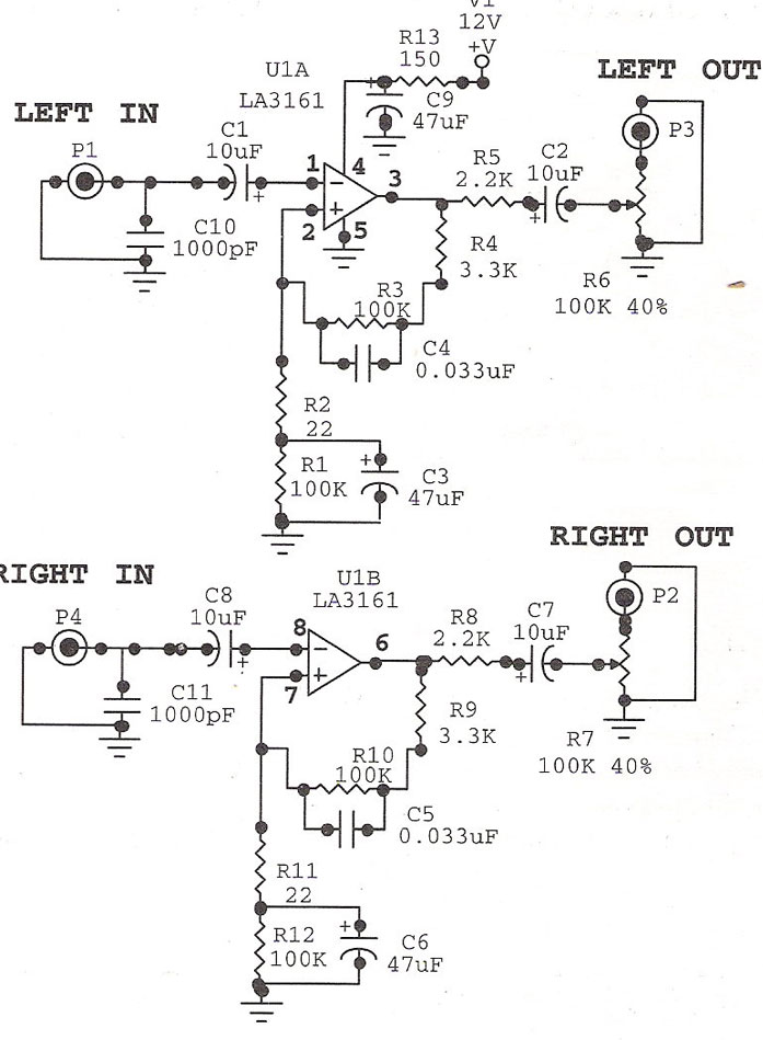
Preamplifier with LA3161. Preamplifiers are utilized to amplify low-level signals, such as those from microphones and tape heads, before they are sent to power amplifiers. The LA3161 is a versatile integrated circuit designed for use in audio preamplification applications. It...
This assembly is designed for amateurs who possess a collection of vinyl records and wish to convert them into a digital format on a personal computer. Alternatively, they may want to enjoy an old, cherished LP collection through their...
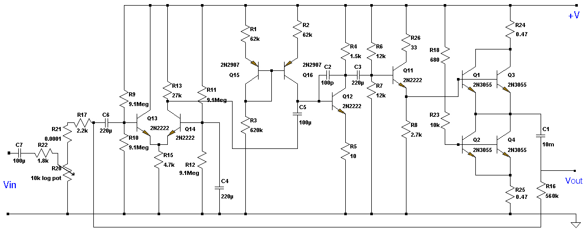
This Class A preamplifier features a symmetrical design. The input differential stages utilize dual transistors, T1 and T2. Polarization correction is crucial due to amplification discrepancies and is managed by transistor T12. Potentiometer P2 adjusts the output voltage to...
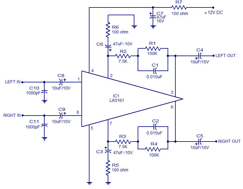
The LA3161 is an integrated two-channel preamplifier designed for car stereo applications. It operates on a 12V DC power supply. The LA3161 preamplifier is specifically engineered to enhance audio signals in automotive environments, ensuring optimal sound quality for car stereo...
Warning: include(partials/cookie-banner.php): Failed to open stream: Permission denied in /var/www/html/nextgr/view-circuit.php on line 713
Warning: include(): Failed opening 'partials/cookie-banner.php' for inclusion (include_path='.:/usr/share/php') in /var/www/html/nextgr/view-circuit.php on line 713