
noise LM386 audio amplifier not amplifying
The LM386 is a low-voltage audio power amplifier designed for battery-powered applications. In this setup, it is essential to ensure that the power supply voltage remains within the specified range to avoid overheating and distortion. The addition of capacitors serves to stabilize the power supply and filter out noise, which can improve audio quality.
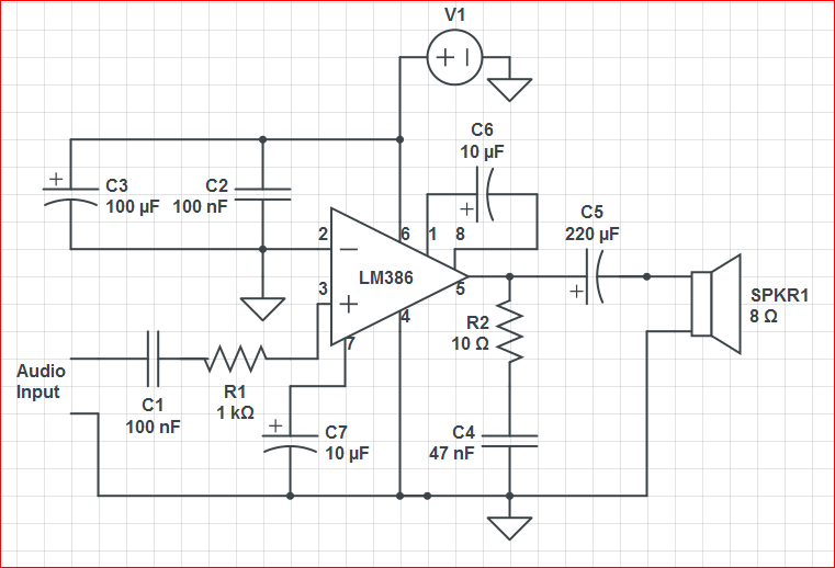
The circuit configuration includes a gain-setting capacitor (10 µF) connected between pins 1 and 8 of the LM386, which sets the gain to approximately 200. The input audio signal is fed through a 1kΩ resistor, which is a common practice to limit the input current and protect the IC.
The choice of speakers is crucial; a 0.2W, 8Ω speaker may not provide sufficient output for the desired volume levels. It is advisable to use speakers rated for higher power (e.g., 1W or more) to match the output capabilities of the LM386. Additionally, ensuring that the speakers are compatible with the amplifier's output impedance will enhance performance.
The reported issue of intermittent loud sounds when nudging the power cable suggests potential mechanical connections or grounding issues. It may be beneficial to inspect all connections, ensuring that they are secure and that there are no shorts or loose wires on the breadboard.
For further troubleshooting, it is recommended to measure the voltage at various points in the circuit while monitoring the audio output. This can identify where the signal may be attenuated or distorted. Using a more reliable power source, such as a regulated DC power supply, can also help eliminate variables related to power fluctuations.
In summary, ensuring proper connections, using suitable speakers, and maintaining stable power supply voltages are critical factors in achieving the desired audio amplification and quality from the LM386 circuit.First I tried connecting the circuit to a 9V battery. (Multimeter reads around 8. 3 Volts, which is in the operating voltage range of the LM386 as per datasheet) The result I have is lots of noise, sometimes cracks and pops and a barely audible sound of the audio input (it feels like highly attenuated form of input which is very bad). It doesn`t ev en sound at least equal to the input! I want the gain to be around 200, so I do have a 10$mu$F capacitor across pins 1 and 8 of the LM386. I`ve also tried connecting to a 9. 6V - 250mA rated unregulated DC adapter. The results are almost the same. (though I seem to get a higher voltage here. ) Initially I simply used a in-ear earphone to pick up the mono output. I also tried connecting a small speaker (pictured). It`s apparently a 0. 2W 8$Omega$ speaker. The output is low, but the end result is similar to the earphone output. Here`s a snap of the breadboard. Sorry for the bad quality pic. This config used the DC adapter and a 0. 2W 40$Omega$ speaker. I even checked all parts for continuity using a multimeter. I`m also open to tips on troubleshooting this, since I`m new. Top bus is the Vs and the bottom bus is the common ground. Input audio is connected to the left end of the `green` 1k resistor. Its a very thin wire since its from a small 3. 5mm TRS cable. I don`t want anything super loud, just audible maybe like 2x of the input signal. If so, what kinds of speakers would this amp be capable of driving What would I need to make it sound acceptable Basically, what`s wrong with this circuit UPDATE: I followed all of your suggestions and my setup now consists of an additional 100$mu F$ capacitor in parallel to the power, a 100nF capacitor in series to the input audio signal and a 10$mu F$ capacitor connected to the bypass pin. There was a problem though, the 9. 6V unregulated adapter I use seems to show 22 Volts on the power rails (under load). this seemed to make the LM386 run really loud. I seem to hear the amplified audio at times when I nudge some parts here, but anyhow after sometime, the IC got too hot and so did the 100$mu F$ capacitor at the power supply.
I can`t really tell if it`s all because of a bad quality adapter or the IC or breadboard or capacitors. The capacitors were salvaged from an old PCB board of another circuit. Also since I think the last LM386 got fried, I desoldered another LM386 from another board and I`m keeping it in stock.
This is the last 386 I have in hand now and I don`t wanna screw this up. Now for safe testing, I drew power from laptop USB (5V regulated). the volt at pin 6 of the new 386 shows a solid 5V. Speakers were really quiet so I hooked this up to an AUX cable and listened to it. The output is weird and not satisfactory. The sound seemed to be amplified when I nudge the power cable at pin 6 (ie, peaks of loud sound happens only at the beginning and then it fades to a point; see attached image/sound of the Line in recording) UPDATE-2: I seriously doubt the volume level output of this amp. through the speakers, I don`t think it plays it loud enough. the signal sounds sort of `amplified`, but the speaker doesn`t seem to output it loud. Btw, I tried 9V batteries, 9V battery with 5V DC, 7. 8V DC, 5V DC all sound the same. Is it because of my speakers Also thanks to everyone who suggested adding extra caps to the power rails.
that part really helped in filtering a lot of noise. I used a 10$mu$F cap there along with the 100nF cap. Or does adding more caps cause power loss or something 🔗 External reference
Related Circuits
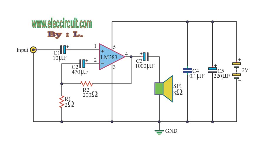
Here is the schematic for an 8 watt audio amp. This amp can be used as a simple booster, the heart of a more complicated amplifier or used as a guitar amp. The circuit can be built on a...
This circuit is a diagram of a mini amplifier. The amplifier circuit has a power output of 10 watts and is well-suited for car audio applications. It utilizes the TDA2009A integrated circuit as the power amplifier. To prevent excessive...
The circuit operates with a 9-volt power supply using the LM386 amplifier IC, which has a power output range of 300-800 mW, depending on the supply voltage, which can vary from 4 to 15 volts. The input signal is...
This is a Class AB audio power amplifier utilizing the Hitachi HA13118 module, suitable for car applications. It can also be used in various other settings. The Class AB audio power amplifier is designed to deliver high-quality sound reproduction while...
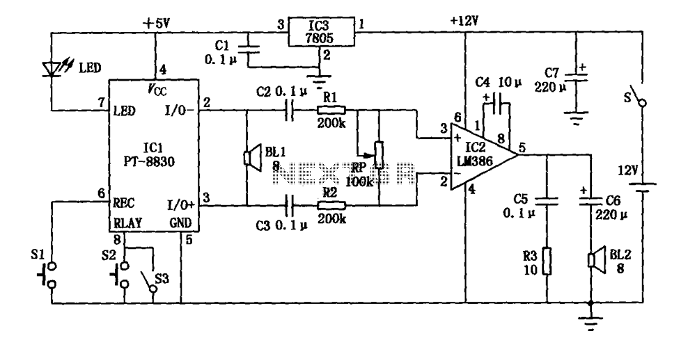
The electronic circuit illustrated in the figure consists of three main components: a voice recording module, an audio power amplifier, and a power supply circuit. The first component, IC1, is a voice recording integrated circuit (IC) of type PT-8815/20/30,...
Building a solid-state linear amplifier. An old Heathkit SB 221 has undergone a major overhaul and redesign, and is now functioning well on 80, 40, 20, and 15 meters; however, it does not operate on 17, 12, and 10...