
Mark 1 Coil Timer

The coil gun circuit design is centered around precise timing control to optimize projectile acceleration and performance. The clock circuit serves as the heartbeat of the system, generating a consistent pulse train that the 8-bit binary counter uses to create discrete timing intervals. Each interval allows for fine-tuning of the coil activation times, which is crucial for achieving the desired projectile speed and efficiency. The use of pull-up resistors on the output lines of the counter ensures that the system remains stable and resistant to noise, which is especially important in high-speed applications where electromagnetic interference could disrupt operation.
The integration of JK flip-flops provides a robust mechanism for controlling coil activation and deactivation, allowing for smooth transitions between different states. The careful design of the timing decoders ensures that each coil can be activated and deactivated with precision, minimizing the risk of projectile misalignment and maximizing the overall efficiency of the coil gun. The architecture allows for scalability, enabling additional coils and timing decoders to be added as needed, making it adaptable for various applications. Overall, this circuit design exemplifies a sophisticated approach to coil gun technology, emphasizing the importance of timing and control in achieving optimal projectile performance.This coil gun design uses on/off times that are rather arbitrary. Well, not chosen at random, but the times are calculated in the spreadsheet according to the basic equations of motion. The coils do not turn on/off at identical intervals. The first coil is on for the longest period because the projectile is moving the slowest. It is moving much fa ster through the last coil, so it`s on for the shortest period. We need a circuit to measure out small period of time. It should be easy to change so we can try different timing variations for the best performance. In short, we need switches (not jumpers) to select the start-time and stop-time for each coil. The clock circuit generates a steady stream of pulses. A simple 8-bit binary counter chip will count the pulses one-by-one. Its output is a regular 8-bit binary number, which divides the clock pulses into 256 time intervals. (Or less, if we reset the counter before it reaches maximum count. ) Each line needs a small pull-up resistor to ensure it stays high (a logic-1) when the switch is open. The pull-ups also provide noise immunity from unterminated inputs. The pull-ups come in a sip (single in-line package) for 8, 9 or 10 resistors at a time, with one pin tied to Vcc.
The output of the 8-bit comparator goes to a latch. The comparator`s output remains high (logic 1) for only one clock cycle. The latch stays high until another comparator turns it off. You can use several of these coil timer decoders to provide all the necessary timing for the latches. Each coil latch takes two time decoders: one time decoder turns it on, and one time decoder turns it off.
So four coils would need at most eight decoder circuits. However, usually one coil turns off at the exact time another turns on. So you only need one more time decoder than coils. My prototype uses three coils, so I used four time decoders. An extra time decoder is shown in the figure below, to show how additional decoders could be added. My design always energizes two coils together (to keep the projectile in the "sweet spot"). It begins by turning on the first two coils. Then it turns off coil 1 while it turns on coil 3, leaving coil 2 and 3 on together. The JK flip flops control the coils. The J input turns on the latch, and the K input turns it off again. Not shown for simplicity, is their clock input lines, which are connected to the high speed free-running clock oscillator. The Reset line to each latch is also not shown. It should be connected to the reset signal from the trigger. This will hold them in a known good state before the first firing after power-up. 🔗 External reference
Related Circuits
When the game timer is reset, two actions must occur: the 4017 counter must return to zero, and the 4060 astable/divider must also reset to zero. If the 4060 continues running, it will become unsynchronized with the 4017, leading...
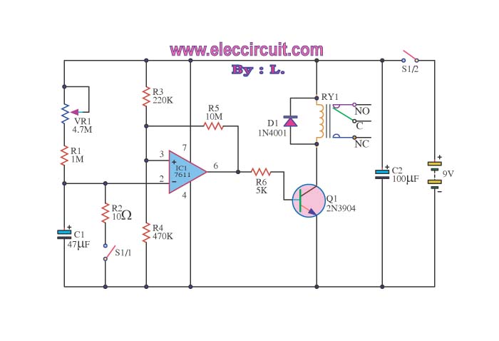
When switch S1/2 is activated, it powers the circuit C1, which utilizes the UA741 operational amplifier for voltage comparison. Pin 3 serves as the non-inverting input, while pin 2 is the inverting input. The voltage at pin 3 is...
This is a lamp timer capable of operating two separate relay switches. Outputs can be in three (or restricted to two) states: OFF, delayed ON and constant ON. Delayed ON mode is indicated by the LEDs. The source code...
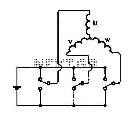
The connection of the stator coils is illustrated, showing the structure and interconnections of the stator coil. Figure A depicts a triangular connection, while Figure B demonstrates a star connection, presenting two forms of star connection. The stator coils in...
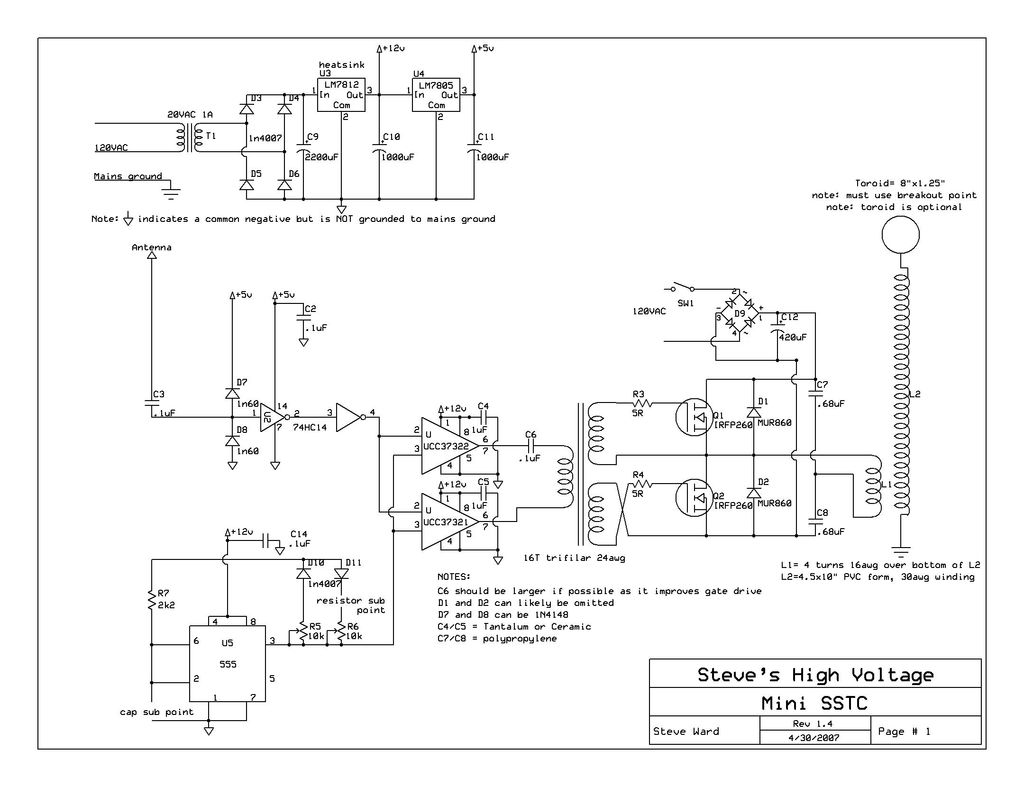
This instructable provides detailed instructions for constructing a solid-state Tesla coil based on Steve Ward's mini SSTC schematic. The solid-state Tesla coil (SSTC) is an advanced high-frequency resonant transformer that operates without the need for mechanical components such as spark...
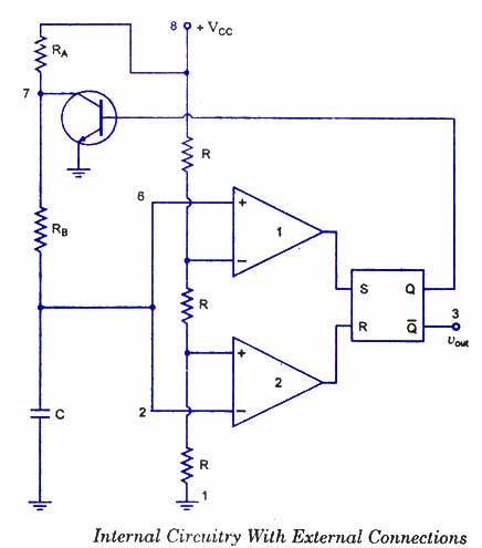
The 555 timer is a highly versatile integrated circuit that can be utilized to construct a wide variety of circuits. It can be effectively used without a detailed understanding of the function of each pin. The 555 timer is commonly...