
games timer 4

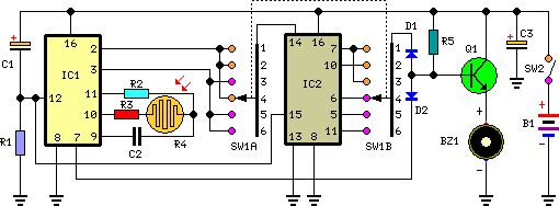
To understand the operation of a rotary switch, familiarity with switch types is necessary. The diagram illustrates four common types of switches: an SPST (single pole single throw) switch has one input connection (pole) and one output connection (throw), functioning as a basic ON/OFF switch. A DPST (double pole single throw) switch features two ganged input connections, allowing simultaneous switching. In a rotary switch, output connections are referred to as ways. The switch can have a total of 12 ways, with 1, 2, 3, or 4 poles available. A 2-pole rotary switch can switch each pole to one of 6 ways, where switching pole A from output 1 to output 2 causes pole B to switch from output 6 to output 7 concurrently. This 2-pole 6-way switch is utilized in the game timer circuit.
Identifying key sections in the circuit is important, starting with the 2-pole 6-way rotary switch. Pole A selects the appropriate RT value, ensuring that only one timing resistor is active in the circuit. For instance, selecting the 18kΩ resistor results in a 1-minute timed interval. Pole B serves as an ON/OFF switch for the circuit. The ways numbered 8, 9, 10, and 11 are interconnected, ensuring that the power supply remains connected regardless of the selected timed period (30 seconds, 1 minute, 2 minutes, or 3 minutes). When the switch is turned to connect pole A to way 1, pole B simultaneously connects to way 7, cutting off the power supply and turning the circuit OFF. One switch position remains unused, which could serve as a second OFF position. However, there is a method to modify the rotary switch's behavior to prevent the spindle from reaching this final position, which will be explained in a subsequent section.
This circuit design emphasizes the synchronization between the 4017 counter and the 4060 astable/divider, ensuring accurate timing for the game timer. The careful selection of resistor and capacitor values is critical for achieving the desired timing intervals. The rotary switch's configuration allows for easy selection of timing periods while maintaining control over the circuit's power state.When the games timer is RESET, two things must happen. The 4017 counter must go back to zero and the 4060 astable/divider must go back to zero. (If we left the 4060 running, it would not be synchronised with the 4017 and erratic times would result. ) The 4017 is rising edge triggered. As a result, LED number 0 goes OFF and LED number 1 goes ON when the first rising edge is received from the 4060. As you can see, this occurs when the time elapsed is equal to half the period of the 4060 pulses. Work through this explanation again if you are unsure about why the total timed period is equal to 8. 5 times the period of the 4060 pulses, rather than 10 times the period of these pulses. Resistors are available at low cost in a wide range of values. Usually, any resistor from 1W to 10MW costs the same. The range of capacitor values is more restricted and larger value capacitors cost more. When you select components for a resistor/capacitor combination, it often makes sense to choose the capacitor first and to start by choosing a relatively small value.
You need to think clearly to follow through these calculations. What you end up with are resistor and capacitor values which allow the games timer to count through a reasonably accurate timed period of 1 minute. These magic numbers are: Once you have established the RT and CT values you need for a timed period of 1 minute, it is much easier to work out the values you need for the other timed periods, 30 seconds, 2 minutes and 3 minutes: To understand how to use a rotary switch, you need to know a bit more about how switches are described.
The diagram below shows four common types of switches: In an SPST, or single pole single throw switch, there is a single input connection, called a pole, and a single output connection, called a throw. An SPST switch is a straightforward ON/OFF switch which can be used to make or break a single connection.
In a DPST switch, the two input connections, or poles, are ganged together, so that they switch simultaneously, either both ON, or both OFF. Simultaneous action, or `ganging` is indicated by the dotted line linking the two parts of the switch.
In a rotary switch, the output connections are usually called ways, instead of throws. The construction of the switch provides a total of 12 ways, but there may be 1, 2, 3 or 4 poles: Alternatively, the rotary switch can be constructed with 2 poles, allowing each pole to be switched to any one of 6 ways. Note that the two poles are ganged. If pole A is switched from output 1 to output 2, pole B switches simultaneously from output 6 to output 7, and so on.
This is a 2-pole 6-way switch and is the kind of switch you are going to use in the games timer circuit. Although the diagram looks complicated, you should be able to identify the important sections of the circuit.
Look first for the 2-pole 6-way rotary switch. Pole A is used to select the appropriate value for RT. Only one of the timing resistors can be in the circuit. For example, if the switch is operated so that the 18kW resistor is selected, the timed interval will be 1 minute. The second pole of the rotary switch, pole B, is used as an ON/OFF switch for the circuit. The ways numbered 8, 9, 10 and 11 are joined together, so that the power supply will be connected to the circuit for any of these switch positions.
In other words, it doesn`t matter which timed period you select 30 seconds, 1 minute, 2 minutes, or 3 minutes, the power supply will remain connected. Turning the switch so that pole A is connected to way 1 simultaneously connects pole B to way 7. In this position, the power supply is disconnected and the circuit is OFF. There is one unused switch position. This could be used as a second OFF position, but there is way of altering the behaviour of the rotary switch so that you can`t turn the spindle into the final position.
You will find out how to do this in a later section of this pra 🔗 External reference
Related Circuits
Six timing positions suited to different skin types; timing affected by sunlight intensity. This timer was designed for individuals seeking to achieve a tan. The electronic timer circuit described is intended for use in tanning applications, specifically designed to cater...
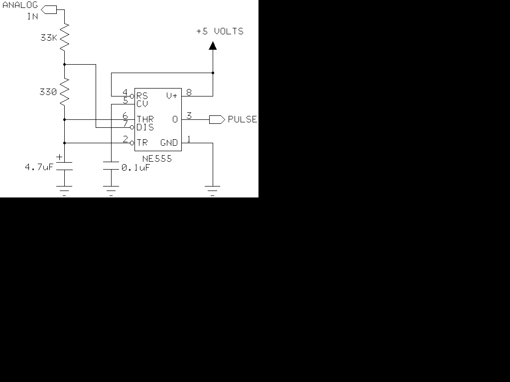
The 555 timer generates positive pulses. The pulse width is inversely proportional to the difference in voltage between the "ANALOG IN" voltage and the voltage across a 4.7 µF capacitor (approximately 2.5 volts). To calibrate this circuit, connect it...
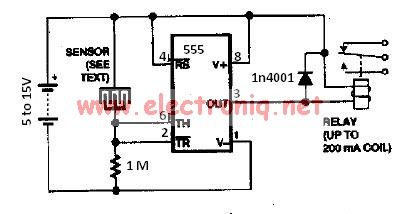
The water sensor circuit utilizes a 555 timer circuit along with common electronic components. It consists of two metal electrodes positioned closely enough that a drop of water can create a conductive bridge between them. If the water is...
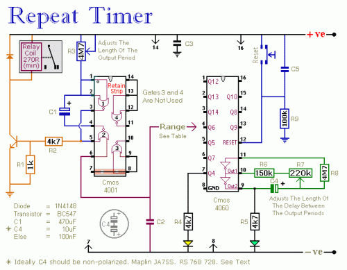
The following circuit illustrates a repeating interval timer circuit diagram utilizing the CMOS 4060 integrated circuit (IC). Features include its foundation on the CMOS 4060 IC and a 14-bit binary counter. The CMOS 4060 IC is a versatile component widely...
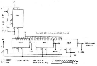
This circuit is designed to provide long time delays using the integrated circuit Timer 555. It utilizes the NE555 to generate pulse frequencies, which are then divided by a 4017 decade counter to achieve the desired delay. The component...
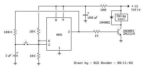
This 555 timer circuit activates a relay upon pressing a button. The threshold and trigger inputs, pins 2 and 6, are maintained at half the supply voltage by two 10K resistors. When the output is high, a capacitor charges...