
max 232 interfacing with
The MAX232 integrated circuit is essential in bridging the communication gap between microcontrollers and RS-232 devices. Its architecture ensures that voltage levels are appropriately adjusted to meet the RS-232 specifications, which are significantly different from the TTL logic levels used in microcontrollers. The presence of two receivers and two transmitters allows for flexible communication setups, enabling the design of systems that require dual-port functionality.
In the circuit design, the use of five external 10µF capacitors is crucial for the operation of the internal charge pump, which generates the necessary voltage levels for signal conversion. These capacitors must be connected correctly to ensure stable operation. The MAX232 is typically powered by a 5V supply, and proper grounding is essential to prevent signal integrity issues.
The connections to the microcontroller and the DB9 connector must be made with attention to detail, ensuring that the data flow is correctly established. The microcontroller's UART (Universal Asynchronous Receiver-Transmitter) pins are directly linked to the MAX232, allowing for seamless data transmission and reception. The functionality of control signals like RTS and CTS enhances the reliability of the communication, especially in environments where multiple devices may be interacting over a shared medium.
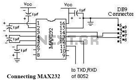
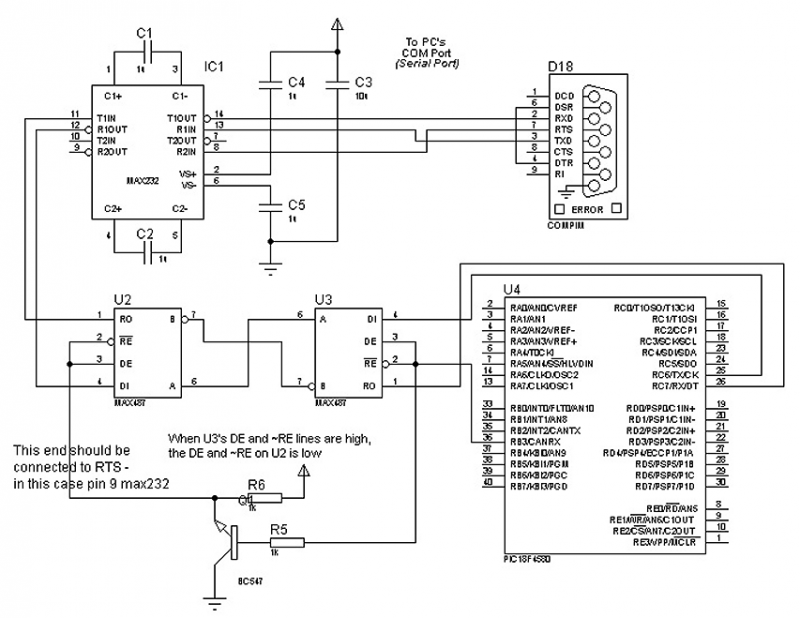
In summary, the MAX232 circuit serves as a vital component in serial communication applications, providing the necessary voltage level conversion and facilitating reliable data exchange between microcontroller systems and RS-232 compliant devices. Proper implementation of this circuit can significantly enhance the performance and robustness of communication systems in various electronic applications.Schematic MAX232 is used to interface the microcontroller to standard RS-232 port of personal computer. It is a signal level converter necessary for conversion between TTL and RS-232 standards. The MAX232 requires 5 external 10uF capacitors. These are used by the internal charge pump to create +10 volts and -10 volts. The MAX232 includes 2 receivers and 2 transmitters so two serial ports can be used with a single chip.
We will only use one transmitter for this project. The only connection that must be made to the 8052 is one jumper from pin 3 of the 8052 to pin 11 of the MAX232. The circuit diagram shown below illustrates the connection of RS232 with microcontroller and serial port DB9 connector.
Data is transmitted and received on pins 2 and 3 respectively. Data Set Ready (DSR) is an indication from the Data Set (i. e. , the modem or DSU/CSU) that it is on. Similarly, DTR indicates to the Data Set that the DTE is on. Data Carrier Detect (DCD) indicates that a good carrier is being received from the remote modem. Pins 4 RTS (Request To Send - from the transmitting computer) and 5 CTS (Clear To Send - from the Data set) are used to control. In most Asynchronous situations, RTS and CTS are constantly on throughout the communication session. However where the DTE is connected to a multipoint line, RTS is used to turn carrier on the modem on and off.
On a multipoint line, it`s imperative that only one station is transmitting at a time (because they share the return phone pair). When a station wants to transmit, it raises RTS. The modem turns on carrier, typically waits a few milliseconds for carrier to stabilize, and then raises CTS.
The DTE transmits when it sees CTS up. When the station has finished its transmission, it drops RTS and the modem drops CTS and carrier together. Clock signals (pins 15, 17, & 24) are only used for synchronous communications. The modem or DSU extracts the clock from the data stream and provides a steady clock signal to the DTE.
Note that the transmit and receive clock signals do not have to be the same, or even at the same baud rate. Note: Transmit and receive leads (2 or 3) can be reversed depending on the use of the equipment - DCE Data Communications Equipment or a DTE Data Terminal Equipment.
🔗 External reference
Related Circuits
This resource provides a variety of PIC Microcontroller tutorials that cater to both beginners and advanced users. These tutorials enable individuals to gain expertise in microcontroller programming and circuit design without the need for costly embedded system courses. The tutorials...
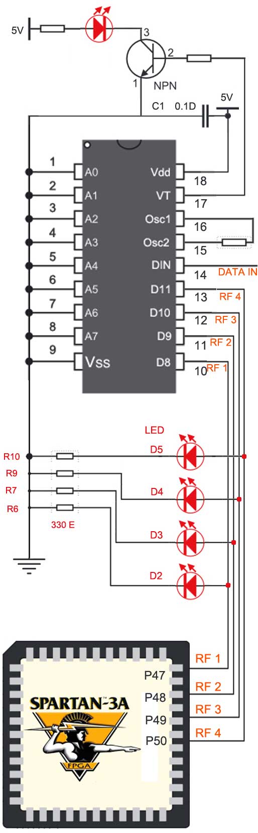
The RF module operates at radio frequencies, with a frequency range between 30 kHz and 300 GHz. In this RF system, digital data is represented as variations in the amplitude of a carrier wave, a modulation technique known as...
This application note provides valuable PC board layout, bypassing, and decoupling guidelines for customers who are implementing high-speed data converters in their designs. High-speed data converters are critical components in modern electronic systems, requiring careful consideration of their integration into...
The circuit in Figure 1 is an RS-232/485 converter that uses the transmitted signal itself to control the flow. The circuit uses MAX232 and MAX483 interface circuits, IC1 and IC2 from Maxim Integrated Products to convert between the ICs'...
This document presents a well-defined printed circuit board layout for the implementation of the MAX8632 Integrated DDR Power Supply. The MAX8632 chip serves as a comprehensive DDR power supply solution, employing a synchronous buck controller to produce the VDDQ...
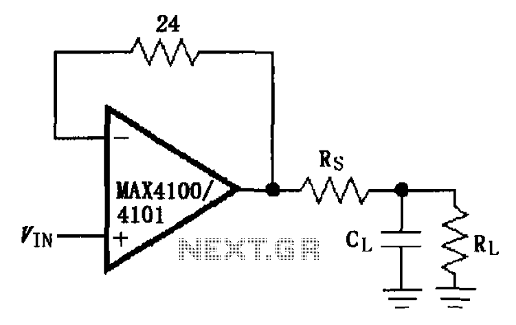
The MAX4100/4101 operational amplifiers utilize a capacitive load drive circuit with an isolation resistor Rs. The MAX4100 and MAX4101 can handle maximum capacitive loads of 5pF and 20pF, respectively, but are susceptible to overshoot and ringing oscillations. To mitigate...