
MAX2606 VHF FM Transmitter
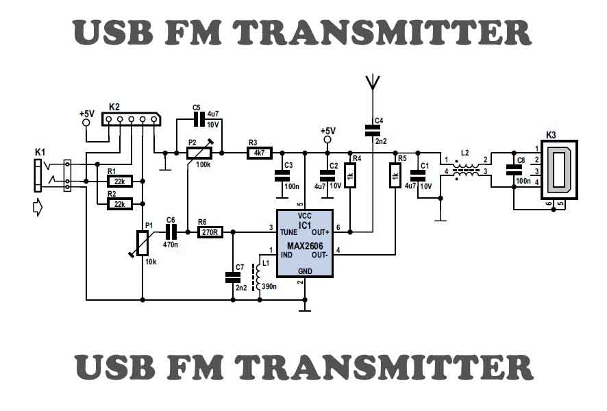
The circuit design centers around the use of the MAX2606 integrated circuit, which simplifies the construction of a frequency-modulated oscillator. The oscillator operates within the VHF frequency range, essential for testing various VHF receivers without reliance on local radio signals. The choice of the external coil is critical, as it directly influences the operational frequency. The MAX2606 requires a coil with an inductance value that can be fine-tuned, allowing for a narrow frequency adjustment of ±3 MHz around the set frequency.
The power supply design incorporates a 9-V battery, with the BC238C transistor serving as a voltage regulator to maintain a stable output of approximately 4 V, thereby ensuring consistent oscillator performance. The use of decoupling capacitors (1 nF) at the power supply and tuning voltage pins is essential for minimizing noise and enhancing frequency stability, which is particularly important in RF applications.
The tuning voltage applied to pin 3 allows for frequency adjustments within a specific range, facilitating the oscillator's adaptability to various testing scenarios. The symmetric output configuration, achieved through the OUT+ and OUT pins, allows for flexibility in signal extraction, with the option to utilize capacitors and pull-up resistors to optimize the output signal for further processing or transmission.
Overall, this oscillator circuit is a robust solution for VHF receiver testing, providing essential frequency modulation capabilities while allowing for user-defined adjustments through external components. The design's emphasis on stability and adaptability makes it a valuable tool in RF engineering and testing applications.To be independent of the local radio stations for testing VHF receivers, you need a frequency-modulated oscillator that covers the range of 89. 5 to 108 MHz ” but building such an oscillator using discrete components is not that easy. Maxim now has available a series of five integrated oscillator building blocks in the MAX260x serieswhich cover the frequency range between 45
and 650 MHz. The only other thing you need is a suitable external coil, dimensioned for the midrange frequency. The MAX2606 covers the VHF band, although the frequency can only be varied by approximately ±3 MHz around the midrange frequency set by the coil L. The inductance values shown in the table can serve as starting points for further experimenting. The SMD coils of the Stettner 5503 series are suitable for such oscillators. In Germany, they are available from BG rklin ( with values between 12 nH and 1200 nH. You can thus directly put together any desired value using two suitable coils. If you want to wind your own coils, try using 8 to 14 turns of 0. 5-mm diameter silver-plated copper wire on a 5-mm mandrel. You can make fine adjustments to the inductance of the coil by slightly spreading or compressing the coil.
The circuit draws power from a 9-V battery. The BC238C stabilises the voltage to approximately 4 V. Although the MAX2606 can work with a supply voltage between +2. 7 V and +5. 5 V, a stabilised voltage improves the frequency stability of the free-running oscillator. The supply voltage connection Vcc (pin 5) and the TUNE voltage (pin 3) must be decoupled by 1-nF capacitors located as close as possible to the IC pins. The tuning voltage TUNE on pin 3 may lie between +0. 4 V and +2. 4 V. A symmetric output is provided by the OUT+ and OUT pins. In the simplest case, the output can be used in a single-ended configuration. Pull-up resistors are connected to each of the outputs for this purpose. You can use a capacitor to tap off the radio signal from either one of these resistors. Several milliwatts of power are available. At the audio input, a signal amplitude of 10 to 20 mV is enough to generate the standard VHF frequency deviation of ±40 kHz.
🔗 External reference
Related Circuits
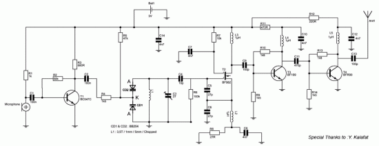
The most important part of this 88-108 transmitter is the Colpitts oscillator. Capacitors C3, C4, C5, C6, and diodes CD1 and CD2, along with inductor L1, determine the transmission frequency. The RF oscillator. The Colpitts oscillator is a type of...
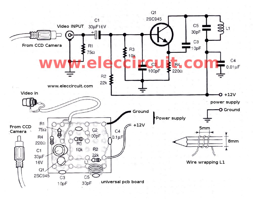
The CCD camera sensor is a very useful device that is compact in size while providing excellent quality. It can be easily installed with a television through the video input terminals, allowing for the transmission of modulated video signals...
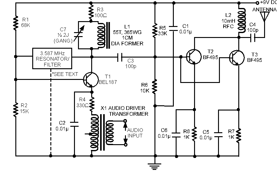
The circuit for a powerful AM transmitter using ceramic resonator/filter of 3.587 MHz is presented here. Resonators/filters of other frequencies such as 5.5 MHz, 7 MHz and 10.7 MHz may also be used. Use of different frequency filters/resonators will...
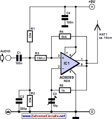
Integrated circuits (ICs) that were once prohibitively expensive for hobbyists are now more affordably priced. A notable example is the AD8099 from Analog Devices, which is available for a modest cost. The AD8099 is a high-speed operational amplifier (op-amp)...
A use has been found for a collection of DIP-style RF relays acquired from a discount electronics shop. These relays are completely sealed and RF shielded, featuring low contact capacitance, making them suitable for VHF frequencies. They operate at...

T1 is a low impedance output transformer with a conversion ratio of 5000 to 8 ohms. The low impedance output transformer, T1, is designed to match the output of an audio amplifier to the impedance of the speaker load. The...