
88 108 MHz FM transmitter BF982 BF199 BFR90

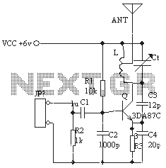
The Colpitts oscillator is a type of electronic oscillator that utilizes a combination of capacitors and an inductor to generate a sine wave output. In the context of an 88-108 MHz FM transmitter, the oscillator is crucial for establishing the carrier frequency of the transmitted signal, which is typically within the FM broadcast band.
In this circuit, capacitors C3, C4, C5, and C6 are arranged in a manner that sets the oscillation frequency. The values of these capacitors, along with the inductance of L1, form a resonant LC circuit. The resonant frequency can be calculated using the formula:
\[ f = \frac{1}{2\pi\sqrt{LC}} \]
where \( f \) is the frequency, \( L \) is the inductance, and \( C \) is the total capacitance of the capacitors in the circuit. The combination of these components allows fine-tuning of the frequency, which is essential for compliance with FM broadcasting standards.
Diodes CD1 and CD2 may serve multiple functions in this circuit. They could be employed for frequency stabilization, providing feedback to the oscillator, or acting as part of a modulation scheme. Their placement and characteristics will significantly influence the performance and stability of the oscillator.
Additionally, the RF oscillator's output is typically fed into a power amplifier stage to boost the signal before transmission. This stage ensures that the signal can be radiated effectively to cover the desired area. Proper filtering and impedance matching are also necessary to ensure that the transmitter operates efficiently and minimizes interference with other frequencies.
Overall, the design of the Colpitts oscillator in this 88-108 MHz transmitter is fundamental to achieving stable and reliable frequency generation, which is vital for effective FM transmission.The most important part of this 88-108 transmitter is the Colpitts oscillator. C3,C4,C5,C6,CD1-CD2 ans L1 determine the transmission frequency. The RF Osci. 🔗 External reference
Related Circuits
Almost any 2x16 character LCD module with Hitachi HD44780 controller chip will work. The LCD pin numbers on the schematic are not valid for all LCD modules. Please check the actual signal names on your particular LCD module. The...
The U2745B is a Phase-Locked Loop (PLL) transmitter integrated circuit (IC) designed specifically for low-cost radio frequency (RF) data transmission systems, supporting data rates up to 20 kBaud. It operates within a transmitting frequency range of 310 MHz to...
In the transmitter schematic, a ballast resistor is not depicted because most small laser power supplies are typically equipped with an integrated ballast resistor. However, variations in power supply designs may require the addition of an external resistor. In laser...
The ordinary triode 3DA87C is utilized to create a long-range FM transmitter circuit, which functions as a standard three-point oscillator circuit. This remote transmitter circuit is capable of large current emissions, achieving a range of up to 1 kilometer...
Here are the schematics for infrared remotes. This remote transmits a tone using an infrared LED. This tone is decoded by the receiver. Since the receiver only switches when it "hears" the tone, there are no accidental activations. The schematic...
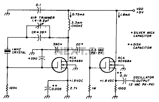
This stable oscillator circuit exhibits less than a 1 Hz frequency change over a VDD range of 3 to 9 volts. Stability is attributed to the use of MOSFET devices and stable capacitors. The described oscillator circuit is designed to...