
MAX3420 Maxim USB Peripheral Controller
The MAX3420 USB peripheral controller is designed to facilitate the integration of USB capabilities into electronic systems with minimal complexity. It operates using an SPI (Serial Peripheral Interface) bus, which allows for efficient communication with a host microprocessor or microcontroller. This chip is particularly advantageous for applications requiring USB connectivity, as it abstracts much of the complexity associated with USB protocol handling.
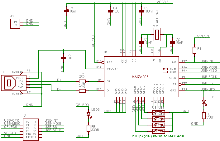
To utilize the MAX3420, it is imperative to ensure that the system is configured correctly. The chip operates at a supply voltage of 3.3V, making it compatible with a wide range of modern microcontrollers. The pin configuration of the MAX3420 is designed for direct compatibility with the Digilent XUP-V2Pro FPGA development board, specifically through header J5, thus simplifying the hardware setup for developers.
Integration of the MAX3420 into a project requires the implementation of a kernel driver, which is crucial for enabling data transfer operations. A basic USB driver is provided, which can be easily deployed by downloading the gzipped tar file, decompressing it, and compiling the code with the 'make' command. This process streamlines the setup, allowing developers to focus on application development rather than driver configuration.
Furthermore, the provided EDK (Embedded Development Kit) peripheral includes a dedicated SPI module that interfaces with the MAX3420, ensuring reliable communication between the USB controller and the host microcontroller. Developers are advised to extract the max3420_v1_00_a directory and place it in the pcores directory of their EDK project to facilitate seamless integration.
In summary, the MAX3420 USB peripheral controller chip is an efficient solution for adding USB functionality to various electronic projects, supported by a straightforward setup process and essential driver resources.The MAX3420 is a USB peripheral controller chip with an SPI bus. This page hopefully contains enough information to help you easily make use of the device in your projects. The MAX3420 provides a very simple approach to adding a USB interface to a circuit. It uses a SPI bus to connect to your system. It does require a reasonable amount of configur ation and control, so you`ll need to connect it to some form of microprocessor/microcontroller. The board is driven by a 3. 3V supply. The connector pin arrangement allows it to be plugged directly into header J5 of a Digilent XUP-V2Pro FPGA development board, as shown in the right-hand photo above. You will need a kernel driver in order to send and receive data from the MAX3420 chip. Below is a basic USB driver that will do this. Hopefully all you`ll need to do is download the gzipped tar, decompress, and type make. The EDK peripheral linked to below contains a SPI module that will talk to the MAX3420. Unpack the file and place the max3420_v1_00_a directory into your EDK project`s pcores directory. 🔗 External reference
Related Circuits
After completing several V-USB tutorials, the next project undertaken was to create a compact USB HID keyboard device that types a password stored in EEPROM each time it is connected. The password can be regenerated by pressing the CAPS...
This integrated circuit is highly efficient and does not require any external glue logic for operation. It features two pins to control a motor: one for direction and the other for stepping pulse triggers. The design is compact and...
The water level controller circuit described here controls the water level inside a tank. There are two modes available with this water level controller circuit. The water level controller circuit is designed to maintain the water level within a specified...

In the design of microcontroller-based electronic projects, the use of a Reset IC is critical for applications that require the microcontroller (MCU) to operate only at its optimum voltage. Without reset circuitry, the MCU may enter a tristate condition,...
USB Battery Charger for Lithium Ion batteries using the LM3622 is a specialized charger circuit designed to operate with power sourced from a USB connection. The current consumption of the LM3622 is limited to 400mA by a resistor (R1),...
Although a matching charger is typically included in the package, some devices can only be charged via a USB port. This is not surprising for USB MP3 players, which need to dock with a PC for file transfers. However,...