
Unipolar Stepper Motor Controllers
The integrated circuit described is designed to efficiently drive stepper motors with minimal external components, making it ideal for compact applications. The two control pins facilitate straightforward operation by allowing users to manage both the direction of the motor and the timing of the stepping pulses. This simplicity is particularly advantageous in scenarios where space and complexity must be minimized.
When dealing with 5 or 8 wire stepper motors, it is essential to recognize their configurations. The 5 wire motor's internal connection of the center taps streamlines the wiring process, but users must be cautious during setup to ensure the correct connections of the remaining coil ends. This may involve some experimentation, as the identification of coil pairs can lead to confusion. The 8 wire motors, while more flexible due to their additional wires, require careful mapping of the center taps and an understanding of coil polarities, which may necessitate testing to achieve optimal performance.
The inclusion of resistors R1 and R2 becomes critical when operating at higher voltages, as they help manage the current and voltage levels to the motor, ensuring reliable operation and protecting the circuit from potential damage. These resistors are particularly useful in high-speed applications, where the response time of the motor is crucial for maintaining performance.
In practical applications, six wire stepper motors are preferred due to their widespread availability and ease of connection. These motors are commonly used in various devices, including printers, where their power capabilities are essential. For those seeking to experiment with stepper motors, non-working dot matrix printers serve as an excellent resource, providing not only motors but also additional mechanical components like belts and gears that can be repurposed for various projects. This approach not only promotes hands-on learning but also encourages innovation in motor control applications.This is a very good integrated circuit. There is no need for any external glue logic to drive the circuit, there is only 2 pins to drive the motor, one for controlling the direction and the other to trigger the stepping pulses. It provides a very compact design that drives 5 or 6 or 8 wire stepper motors. The 5 or 8 wire stepper motors are treated as a variation on the 6 wire motor. That is, the 5 has the two common wires from the coils center taps joined inside the motor (saves joining them outside the motor), however some confusion may occur with the ends of the other coils as to which joins with which, however trial and error to determine this will not hurt anything. In the 8 wire motor case the joined center taps will have to worked out by you. You will know which coil is joined to which coil, however experimentation may be required to determine polarity.
The resistors R1 & R2 are only necessary if the supply voltage to the motors is above 10 volts or so, and are really only necessary near max voltages and tuning the response times of the motor for high speeds. See data sheets for details. There should be very little problem getting hold of six wire motors that make the connections obvious.
These motors are by far the most common where any degree of power is required, e. g. in printers. Non-working dot matrix printers are fairly common now-a-days and the motors in them are excellent starting points for experimentation. You will also get belts, pulleys and gears thrown in (may be even a power supply if your are adventurous).
🔗 External reference
Related Circuits
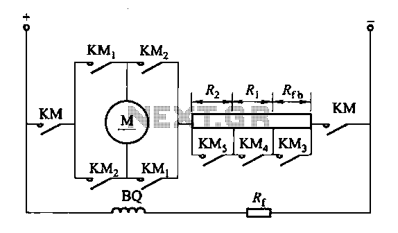
The circuit depicted in Figure 3-200 (a) illustrates the operation of a reverse braking system. When reverse braking is initiated, the forward contacts of contactor KMi open, and the reverse brake contactor KM3 disconnects while the reverse contactor KM2...
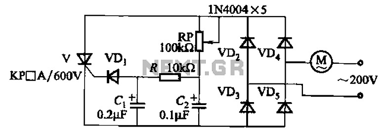
The circuit illustrated in Figure 3-11 employs a unidirectional thyristor control mechanism. An adjustable potentiometer, designated as RP, is utilized to continuously modify the motor speed. The circuit utilizes a unidirectional thyristor, also known as a silicon-controlled rectifier (SCR), which...
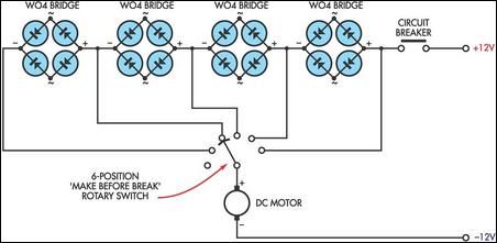
This circuit utilizes the voltage drop across bridge rectifier diodes to create a 5-position variable voltage supply for a DC fan or other small DC motors. While it is not as efficient as a switch-mode circuit, it offers advantages...
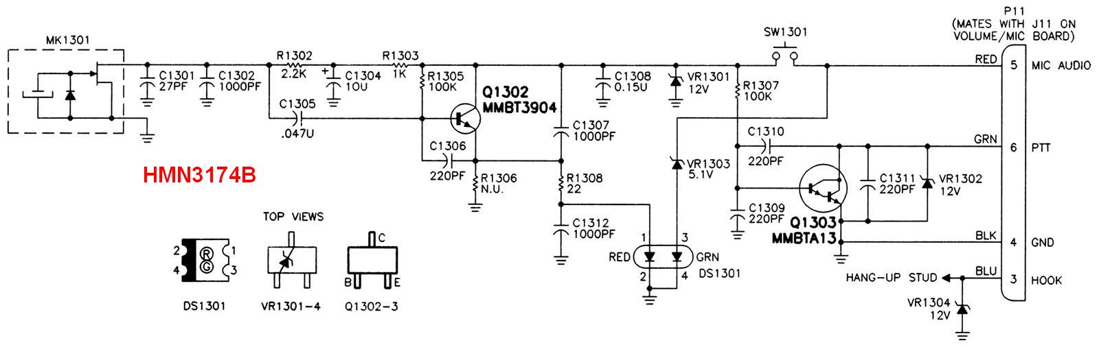
This page focuses on radios marketed in the USA, compiled by residents familiar with these products. Contributions regarding non-USA radios are welcome, and a region-specific page could be created. The MaxTrac, Radius, and GM300 series have inspired additional radio...
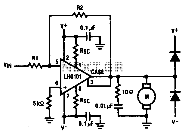
The motor driver amplifier is designed to deliver the rated current to the motor. It is important to manage power dissipation to remain within allowable limits. This precision speed regulation circuit utilizes rate feedback to maintain a constant motor...
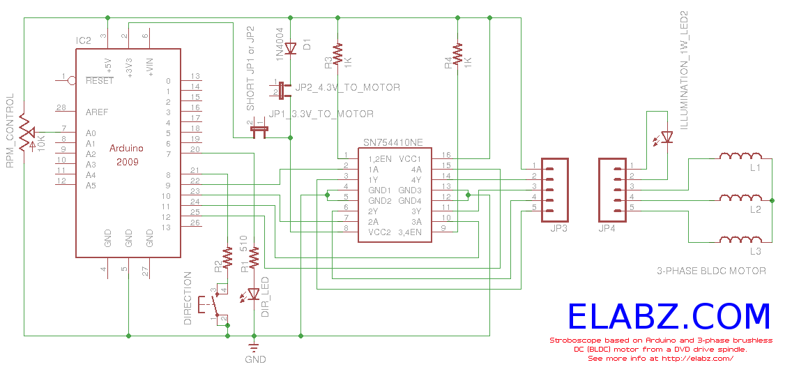
Constructing a stroboscope (zoetrope) using an Arduino and the spindle motor from a damaged Xbox 360 DVD drive. Includes zoetrope animations, Arduino code, and circuit schematic. The project involves utilizing an Arduino microcontroller to control the spindle motor extracted from...