
Reset IC in Microcontroller Application

In a typical schematic for a microcontroller-based project utilizing a Reset IC, the circuit is designed to ensure reliable operation of the MCU under varying power conditions. The Reset IC is connected between the Vcc supply and the reset pin of the MCU. The Vcc line feeds into the Reset IC, which continuously monitors the voltage level.
When the voltage on the Vcc line drops below the specified threshold, the Reset IC generates a low output signal on the reset line, which is connected to the reset pin of the MCU. This low signal holds the reset pin in a reset state, preventing the MCU from executing any code or entering an undefined state. Once the Vcc voltage rises above the threshold, the Reset IC waits for a predetermined period, defined by an internal timing mechanism, before releasing the reset line.
During this time, the MCU remains in a reset state, allowing the power supply to stabilize. After the timing period, the Reset IC pulls the reset line high, allowing the MCU to start executing its program. This mechanism is crucial in preventing erratic behavior during power fluctuations, ensuring that the MCU only begins operation when the supply voltage is stable and within its operational limits.
The choice of Reset IC is important and should match the voltage requirements of the MCU. For microcontrollers with a supply voltage range of 1.8V to 5.0V, selecting a Reset IC with a threshold voltage that corresponds to the minimum operating voltage of the MCU is essential for optimal performance. The Reset IC should also have a fast response time to quickly react to voltage drops, thereby minimizing the risk of the MCU entering an unstable state.
In summary, the integration of a Reset IC into microcontroller-based designs is a fundamental aspect of ensuring reliable operation, particularly in environments where power supply variations may occur.In the design of microcontroller based electronics project, the use of Reset IC is critical for highly critical applications that need to ensure that the MCU will only operate at its optimum voltage. Without the use of reset circuitry, the MCU may go into a tristate of which it may go into abnormal operation.
One example of the use of the Reset IC is that when the input voltage drops below a fixed threshold, the reset IC will assert a reset signal for a fixed period of time after Vcc rises above the fixed threshold value. An example of how a reset circuit is connected is as shown below. During power up, once Vcc exceeds the reset threshold, the reset line will be kept low for a period after which the line will be pulled high.
This resets the MCU after which it will go into normal operation. This operation will ensure that the MCU power supply is monitored and will only go into operation when the Vcc is within the range of its operation. The threshold voltage of the IC is chosen based on the minimum Vcc of the MCU. MCU supply can range from 1. 8V to 5. 0V and a suitable IC can be chosen to monitor the supply voltage to the MCU. A typical range of RESET IC from ST range from 2. 6V to 4. 6V. 🔗 External reference
Related Circuits
When using microcontrollers in designs, a common challenge is displaying user-required data. Solutions such as multiple LEDs, 7-segment displays, or LCD modules can be employed, but displaying a large amount of information simultaneously can pose difficulties. Large LCD modules...

Utilize the Maxim MAX292 switched-capacitor filter integrated circuit to convert a square wave into a sine wave. The operational frequency range of the circuit spans from 5.2282 Hz to 8928.6 Hz when the microcontroller is functioning at a 16-MHz...
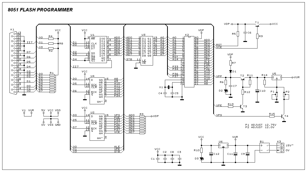
This programmer was designed to be flexible, economical, and easy to build. The programmer hardware utilizes standard TTL series parts, and no special components are used. The programmer is interfaced with the PC parallel port, and there are no...

The YSS247 has several characteristics, including fewer external components compared to similar products. Unlike the SRS5250S, the YSS247 utilizes a single potentiometer to adjust the surround effect. The circuit allows for switching or turning the tone control to modify...

The Atmega8 microcontroller from Atmel features numerous digital and analog input/output lines, making it an ideal choice for developing various measurement equipment. It is essential to have the GCC AVR programming environment installed, as outlined in the article "Programming...
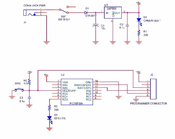
A simple program that will blink an LED. All that is required is a basic JDM programmer, and the setup is ready to go. The circuit requires a power supply, and while a good power generator is recommended, a...