
MAX8743 chip using laptop chipset power supply circuit
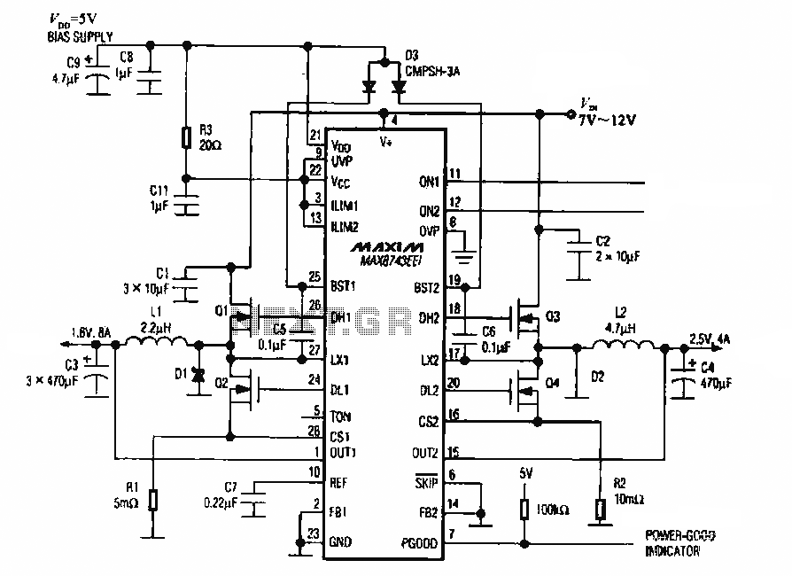
The MAX8743 is a highly integrated power management solution designed specifically for laptop chipsets. This chip features a linear regulator capable of stepping down a 5V input voltage to two lower output voltages: +2.5V and +1.8V, which are commonly required by various components within a laptop system.
The circuit typically consists of the MAX8743 chip connected to the primary 5V power source. Input capacitors are placed near the power pins of the chip to stabilize the input voltage and reduce noise. The output voltage levels are set using external resistors according to the feedback mechanism integrated within the MAX8743.
For the +2.5V output, a feedback network is configured to ensure that the output voltage remains stable under varying load conditions. Similarly, the +1.8V output is generated through a separate configuration of resistors and capacitors, ensuring that both voltages can be supplied simultaneously without interference.
Additionally, the circuit may include bypass capacitors at the output to further filter noise and provide transient response improvement. It is also common to see thermal management features, such as heat sinks or thermal pads, incorporated into the design to dissipate heat generated by the MAX8743 during operation.
Overall, this power supply circuit effectively meets the voltage requirements for modern laptop chipsets, offering efficiency and reliability in a compact design.MAX8743 chip using laptop chipset power supply circuit It is shown using the MAX8743 chip laptop chipset power supply circuit, the 5v power supply, respectively, after the conversion output +2.5 V and +1.8 V power supply.
Related Circuits
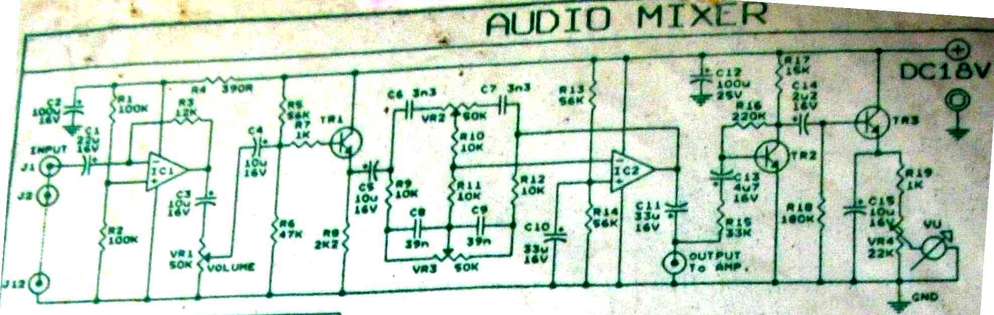
This is audio mixer circuit. The circuit is for one channel input, if you need, for example 5 channel mixer, then you need to build 5 similar circuits. The audio mixer circuit described is designed to handle a single channel...

This is a simple passive headphone distribution box that functions effectively. It has been utilized in various recording studios and constructed for multiple users. The absence of active components ensures minimal failure risk and a quick assembly process. The...
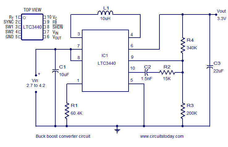
A simple and highly efficient buck-boost converter is implemented using the LTC3440 integrated circuit. The output voltage is set at 3.3V, while the input voltage range can vary from 2.7V to 4.2V. The LTC3440 is a synchronous buck-boost converter designed...
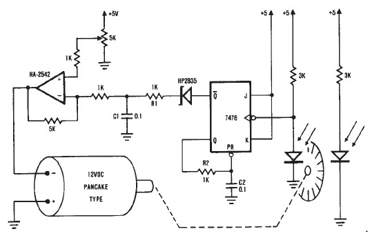
A simple encoder circuit for a DC motor can be constructed using this circuit diagram. The system consists of the HA-2542, a small 12-V DC motor, and a position encoder. During operation, the encoder generates a series of constant-width...
The personal radar system utilizes the PIC microcontroller PIC18F452 as a hobby project. The attached circuit diagram of the radar may appear simple; however, careful analysis of the PIC18F452 radar circuit is necessary to prevent damage. This personal radar...

If the total circuit resistance can be significantly reduced to less than 0.1 Ohm and a load of 0.4 Ohm or less is connected, over 1 kilowatt of free electrical energy can be obtained. There are two discrete voltage...
Warning: include(partials/cookie-banner.php): Failed to open stream: Permission denied in /var/www/html/nextgr/view-circuit.php on line 713
Warning: include(): Failed opening 'partials/cookie-banner.php' for inclusion (include_path='.:/usr/share/php') in /var/www/html/nextgr/view-circuit.php on line 713