
MC CONTROL TRANSMITTER

The described circuit utilizes a free-running multivibrator configuration, which is a type of astable multivibrator that generates a continuous square wave output without requiring an external trigger. This output is utilized to control the power amplifier Q4, which is designed to amplify audio signals effectively. The free-running nature of the multivibrator allows for consistent operation, making it suitable for various audio applications.
The operational range of approximately 1 mile indicates that the circuit is likely intended for use in wireless audio transmission systems, where the amplified audio signal can be transmitted over a significant distance. This range is influenced by the power output of the amplifier, the efficiency of the antenna used, and the surrounding environmental conditions.
Capacitor C6 plays a crucial role in the circuit by tuning the collector of the oscillator to the frequency of a crystal. This tuning is essential for maintaining frequency stability and ensuring that the oscillator operates at the desired frequency. The use of a crystal oscillator provides a precise frequency reference, which is vital in applications where signal integrity is critical.
In summary, the circuit integrates a free-running multivibrator with a power amplifier, utilizing a capacitor for frequency tuning, to create a reliable audio transmission system capable of operating over a distance of approximately 1 mile. The design principles and components referenced are based on established practices in transistor circuit design, as outlined in the literature from Texas Instruments.Free-running multivibrator keys power amplifier Q4 at audio role. Range is about 1 mile C6 tunes collector of oscillator to crystal frequency. -Texas lnstruments Inc. , "Transistor Circuit Design, " McGraw-Hill, N. Y. , 1963, p 361. 🔗 External reference
Related Circuits
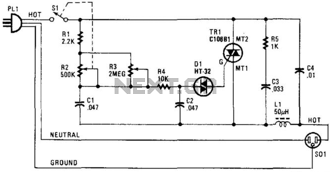
A phase-controlled triac (HT-32) circuit offers control over the effective voltage at the load. It is important to include LI and C4, as they are essential for RFI suppression. The maximum load capacity is approximately 500 W. WARNING: 120...
The circuit was designed to operate a frequency modulation voice transmitter over the FM band within the VHF frequency range. The transmitter is an electronic device. The frequency modulation (FM) voice transmitter circuit operates within the VHF (Very High Frequency)...
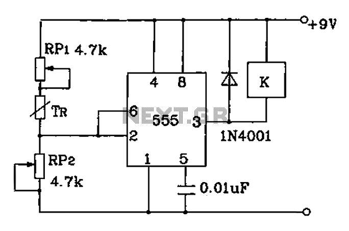
Adjust RP1 and RP2 to set the preset temperature control point. The 555 circuit is configured as a Schmitt inverter circuit that automatically controls a relay device. This forms part of the T-121 temperature control circuit, which includes a...
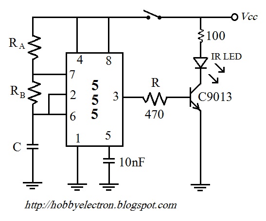
The remote control circuit comprises two main components: a transmitter and a receiver. The transmitter circuit is controlled by an NE555 integrated circuit (IC), while the receiver operates based on the frequency of the signal emitted by the transmitter....
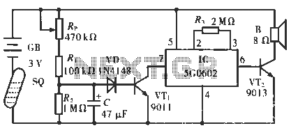
The circuit operates in such a way that when the patient is typically in an upright position, the SQ mercury switch is turned off, resulting in the alarm circuit being inactive. When the patient lies down, the SQ switch...
The MiniBoard, a Motorola 68HC11 Robot Controller board designed by Fred G. Martin, also uses this driver. The day after, I then decided to prepare the page describing how to use C-52 EVB as a robot controller board. I...