
MDRC Mark 4 20 Amp Power Supply
The Mark 4 Power Supply Project features a linear voltage regulation circuit that utilizes the Fairchild "723" regulator, which is known for its stability and reliability. The design includes a primary power input stage that converts the AC mains voltage to a regulated DC output suitable for powering various electronic devices. The output voltage is adjustable, allowing users to set it to the required level for their specific applications.
The over-voltage protection circuit is a critical safety feature, designed to prevent excessive voltage from reaching connected equipment. This circuit consists of a zener diode, resistors, and transistors that work in conjunction to monitor the output voltage. When the output voltage exceeds the predetermined threshold of 15 volts, the zener diode conducts, triggering the transistors to activate a relay that disconnects the power supply. This mechanism ensures that any fault condition leading to over-voltage does not damage sensitive components.
To enhance the performance of the Mark 4 Power Supply, modifications may include improving the layout to minimize electromagnetic interference (EMI) and implementing filtering techniques to reduce noise. Additionally, using higher-quality components for the zener diode and transistors can improve the circuit's response to voltage spikes and enhance overall reliability.
The feedback configuration involving TR10 and TR11 is crucial for maintaining the stability of the output voltage. It is essential to ensure that these transistors are properly biased and that the feedback loop is tightly controlled to avoid oscillations and ensure consistent operation. The design may also benefit from incorporating modern components with better noise characteristics to address feedback from the constructors regarding noise issues.
In summary, the Mark 4 Power Supply Project is a well-established design that has served the amateur radio community for over two decades. The proposed upgrades aim to address specific issues while maintaining the integrity and reliability of the original design. By focusing on enhancing the over-voltage protection circuit and improving noise performance, the updated power supply will continue to meet the needs of constructors and users alike.I was asked by the MDRC committee of the day if I would like to take on the role as Electronic components and project officer, I didn`t see any problem with this and agreed. After being elected into the position I soon found out that a little more time would be required than I expected, most of which was spent answering m
ail. One item that kept popping up was a couple of small problems with a project released prior to my association with the club, being the 1988 Mark 4 Power Supply Project. The following is the upgrade notes to rid the problems without a total rehash. For over 20 years now the Moorabbin and District Radio Club has supplied kits to the amateur fraternity.
Our current mark 4 has been quite popular since its introduction in 1988. However, recent constructor feedback has necessitated the need for an upgrade. The regulator circuit of the mark 4 employs a linear design based on the long standing industry standard "723" regulator from Fairchild (tm). Current trends obviously lean towards Switch Mode designs as they are inherently more efficient, physically smaller and cheaper to produce.
However many switch mode designs are often noisy, even when displaying good regulation characteristics and it is for this reason that we have maintained a linear design. The Mark 4 as with earlier MDRC supplies is equipped with over Volts protection. This prevents the unregulated 24 to 28 Volts DC from causing damage to your equipment in the event of a regulator failure.
It is with this part of the power supply circuit that constructors are experiencing problems, the symptoms are as follows. The over volts protection circuit is a simple resistor, zener diode arrangement with transistor switching.
In the event of a output of more than 15 volts the zener with begin to conduct, once sufficient Voltage is developed across R16 (about 1 Volt) TR11 will be biased on. since TR10 is connected in a feedback configuration with TR11 both transistors and thus the relay will be ON.
This condition will remain until removal of the mains and discharging of capacitors C1-C6. A problem with this type of circuit is its sensitivity to spikes or noise. Spikes, caused frequently by switch bounce, may develop sufficient volts across R15 to switch TR10 & 11 ON. This spike need only be for micro-seconds or less as the BD139 / 140 transistors can now switch in the hundreds of Megahertz range.
🔗 External reference
Related Circuits
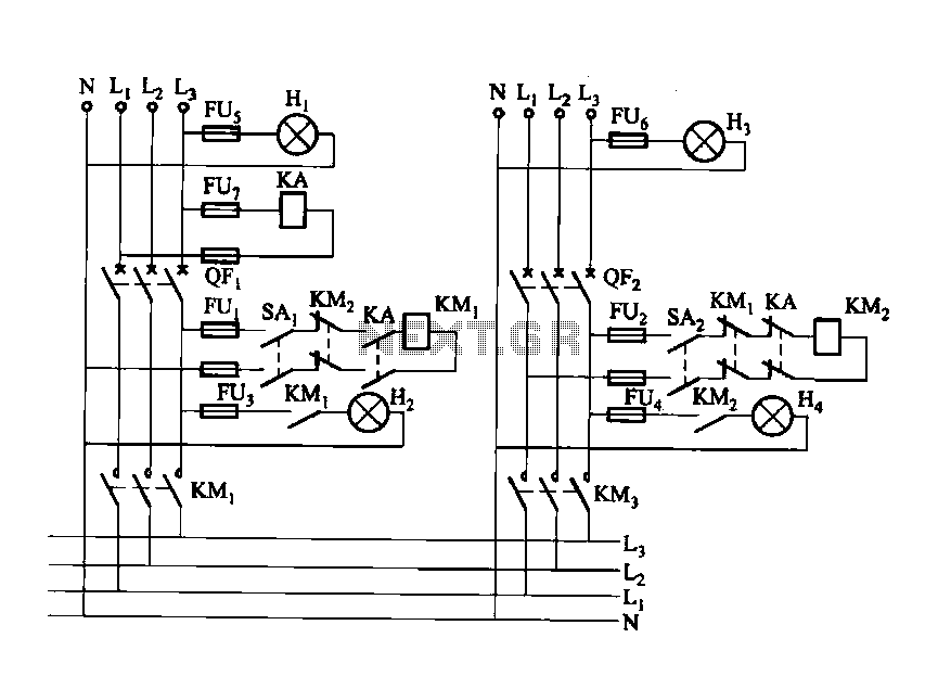
Dual power automatic recovery means one power supply and one standby power supply. When the main power supply is turned off, the standby power supply is automatically activated. Once the main power supply is restored, the system automatically exits...
The sound system features a de-sensitized design with a maximum range that can be increased if desired. It includes two tone controls: one offering a lift of 10 dB and the other providing a subtle cut of 3 dB....
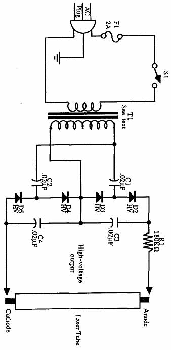
Construct universal power supplies, including low-voltage power supplies for operating electronic equipment. The designs include single- and dual-voltage regulated supplies, an all-purpose adjustable version, and battery pack regulators. A helium-neon laser tube requires a high-voltage power supply for operation....
The JBL "Bass Wave" amplifier is a compact 100-watt amplifier featuring a built-in active filter that includes a single-pole high-pass filter at 10 Hz and a single-pole low-pass filter at 85 Hz. Priced at an affordable $50 USD, it...
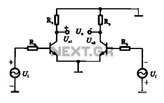
An amplifier circuit is designed to handle an assumed input consisting of two equal and opposite polarity signals, known as a differential mode signal. The two tube collector currents, Ic and IC7, are balanced in such a way that...
The major advantage of amplifiers of this type is that the normal static power dissipation is very low, and the overall power-conversion efficiency is high. Unfortunately, there are also some inherent disadvantages due to the intrinsic dissimilarity in the...