
Memory doorbell circuit
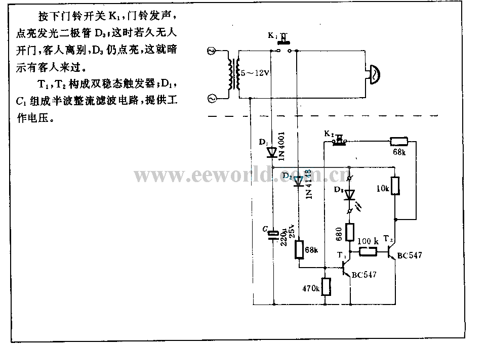
The described circuit functions as a visitor alert system that combines auditory and visual notifications. Upon pressing the doorbell switch K1, an electrical signal is generated, which activates the doorbell sound module. Simultaneously, LED D3 is illuminated, providing a visual cue that the doorbell has been activated.
In the event that no one answers the door, LED D3 continues to stay lit, serving as a reminder of the visitors who have come and left. This feature is particularly useful in scenarios where the homeowner may not have heard the doorbell.
The flip-flop circuit, composed of transistors T1 and T2, plays a crucial role in maintaining the state of LED D3. This configuration allows the LED to remain on even after the doorbell switch is released, effectively latching the state of the circuit until it is reset.
The half-wave rectification filter circuit, formed by diode D1 and capacitor C1, converts the AC voltage from the power supply into a usable DC voltage for the rest of the circuit. This ensures stable operation of the components, particularly the flip-flop and the LED, by smoothing out any fluctuations in the power supply.
Overall, this circuit design is efficient and serves a practical purpose in enhancing home security and visitor management, providing both sound and visual alerts to the homeowner.Pressed doorbell switch K1, the doorbell phonation, lighted up LED D3; if there are nobody to open the door, guests leave, D3 still on, this means there were guests came. Flip-flop is composed of T1, T2; D1, C1 form half wave rectification filter circuit, to support work voltage..
🔗 External reference
Related Circuits
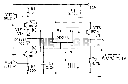
The circuit depicted involves transistors VT1, VT2, and resistor R1, which form a constant current source for charging capacitor C2 in a linear manner. Transistors VT3, VT4, and resistor R2 create a constant current source for discharging capacitor C2,...
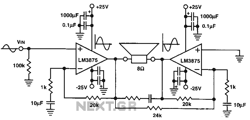
The audio power amplifier delivers 80W of audio power to an 8-ohm load. The LM3875 integrated circuit (IC) requires adequate cooling. It is important to note that in the bridge amplifier configuration, the two connected speakers will produce heat. The...
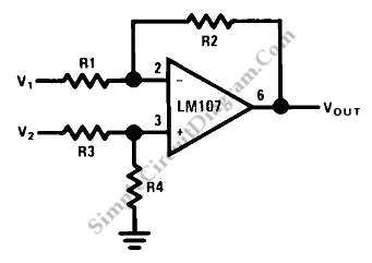
This circuit is a difference amplifier. It functions as an inverting amplifier that enables the subtraction of two voltages, effectively performing a summation. The difference amplifier is a fundamental circuit configuration in analog electronics, primarily used for amplifying the difference...
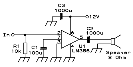
Approximately one watt RMS appears to be a suitable output level, which is also the maximum power that a basic amplifier powered by 12V can deliver to an 8 Ohm speaker. A very low saturation amplifier may reach up...
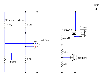
The thermistor utilized has a resistance of 15k ohms at 25 degrees Celsius and 45k ohms at 0 degrees Celsius. A suitable bead-type thermistor can be sourced from the Maplin catalogue. The inclusion of a 100k potentiometer enables this...
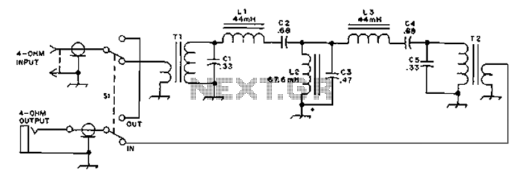
The circuit provides an 8-ohm output for connecting communication receivers and low-impedance speakers or headphones, featuring harmful interference suppression for continuous random voice transmission. The passband ranges from 55 to 2530 Hz with a 3 dB bandwidth. Inductors L1...
Warning: include(partials/cookie-banner.php): Failed to open stream: Permission denied in /var/www/html/nextgr/view-circuit.php on line 713
Warning: include(): Failed opening 'partials/cookie-banner.php' for inclusion (include_path='.:/usr/share/php') in /var/www/html/nextgr/view-circuit.php on line 713