
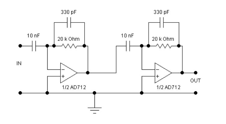
Voice bandpass circuit diagram

The circuit is designed to facilitate audio signal transmission while ensuring compatibility with various low-impedance audio devices. The 8-ohm output is particularly suited for communication receivers, enabling effective audio delivery to both speakers and headphones. The inclusion of interference suppression mechanisms is critical in maintaining audio clarity and preventing degradation of the transmitted signal from external noise sources.
The specified passband of 55 to 2530 Hz indicates the frequency range within which the circuit operates effectively, making it suitable for a wide array of audio frequencies typically encountered in voice communication. The 3 dB bandwidth implies that the circuit will maintain a relatively flat frequency response within this range, ensuring minimal signal loss and distortion.
Inductors L1 and L3, each rated at 4 mH, and inductor L2, rated at 88 mH, play a vital role in the circuit's filtering capabilities. The inductors are configured to manage the impedance and enhance the overall performance of the audio transmission. The lower inductance values of L1 and L3 may be utilized for high-frequency filtering, while the higher inductance of L2 can be responsible for low-frequency response, allowing for a balanced audio output.
Overall, this circuit design is optimized for efficient audio transmission in communication applications, providing a robust solution for connecting to various audio output devices while minimizing interference and maintaining audio integrity across the specified frequency range.8 ohm output for connecting communication receivers and 8 ohm speaker or low impedance phones, harmful interference suppression continuous random voice transmission. Passband 3 55 to 2530Hz, 3dB. L1 and L3 are 4amH the ring. L2 is 88mH the ring.
Related Circuits
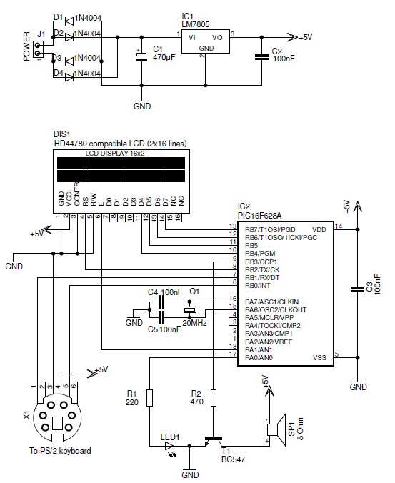
This PIC-based hardware circuit accepts texts from a PS/2 keyboard and converts it into a Morse code audio signal. The described circuit utilizes a PIC microcontroller to interface with a PS/2 keyboard, allowing for the input of alphanumeric characters. The...

The phase and neutral wires from the power source have already been connected to electrical appliances such as fans and light points. According to the UPS connection diagram, an additional phase wire should be connected to those appliances where...
The circuits examined thus far rely on linear feedback for their operation. The magnitude of the signal returned to the negative input is always strictly proportional to the output voltage. Consequently, within the limits defined by the operational amplifier...
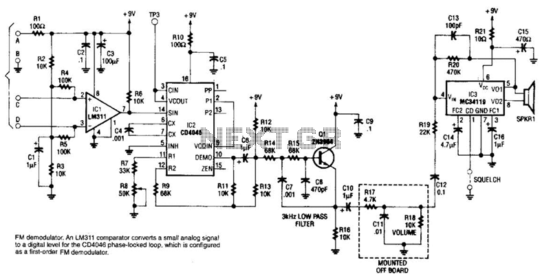
An LM311 comparator converts a small analog signal to a digital level for the DC4046 phase-locked loop, which is configured as a first-order FM demodulator. This demodulator operates with a 50-kHz FM modulated input signal and has applications in...

This inverter circuit is designed to power electric razors, stroboscopes, flash tubes, and small fluorescent lamps using a 12-volt car battery. Unlike conventional feedback oscillator inverters, this design features a separate oscillator from the output stage, allowing for easy...
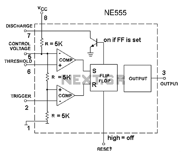
The 555 timer circuit, regardless of the manufacturer, has a consistent internal structure and performance. Various manufacturers produce different models of the 555 timer, including MC555, CA555, XR555, LM555, as well as domestic models like SL555, FX555, and 5G1555....