
Op-Amp Circuit: Difference Amplifier

The difference amplifier is a fundamental circuit configuration in analog electronics, primarily used for amplifying the difference between two input voltages while rejecting any common mode signals. This is particularly useful in applications where precise voltage measurements are required, such as in sensor signal conditioning and operational amplifiers.
The core components of a difference amplifier typically include four resistors and two operational amplifiers (op-amps). The resistors are arranged in a manner that sets the gain of the amplifier and determines the input impedance. The configuration can be represented using the following resistor values: R1 and R2 for the input stage, and R3 and R4 for the feedback stage. For ideal operation, the resistor values should be matched, meaning R1 = R3 and R2 = R4, which ensures that the circuit maintains a balanced response to differential inputs.
In operation, the voltage difference between the two input terminals (V1 and V2) is amplified by the circuit. The output voltage (Vout) can be expressed mathematically as:
Vout = (R2/R1) * (V2 - V1)
This equation highlights the role of the resistor ratios in determining the gain of the amplifier. When V1 and V2 are equal, the output voltage will be zero, demonstrating the ability of the difference amplifier to reject common mode signals.
The difference amplifier finds numerous applications, including data acquisition systems, instrumentation amplifiers, and in scenarios where noise reduction is critical. Its ability to amplify small differential signals in the presence of larger common mode voltages makes it an essential tool in precision measurement and control systems.This is a circuit of difference amplifier. This circuit is an inverting amplifier that allows the subtraction of two voltages and that is the summing.. 🔗 External reference
Related Circuits
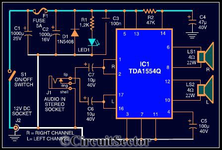
The circuit diagram illustrates a robust stereo amplifier capable of delivering 22W of power. It is based on the widely used single-chip audio power amplifier TDA1554Q (IC1), which is configured as two 22W stereo bridge amplifiers. While listening to...
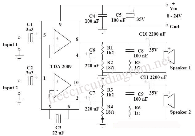
This circuit is a diagram of a mini amplifier. The amplifier circuit has a power output of 10 watts and is well-suited for car audio applications. It utilizes the TDA2009A integrated circuit as the power amplifier. To prevent excessive...
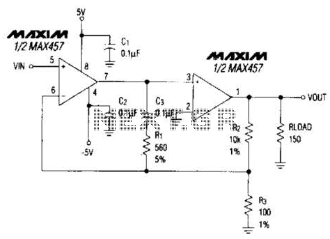
A composite amplifier can be constructed that offers high gain, wide bandwidth, and good DC accuracy by cascading the sections of a dual video amplifier and incorporating two suitable phase compensation components. The operational amplifier drives a 150-ohm load...

This is a linear amplifier that requires advanced knowledge in electronics due to the complexity of the schematic diagram for a handmade circuit. It is advisable to redesign the schematic diagram using circuit design software such as DipTrace, Eagle,...
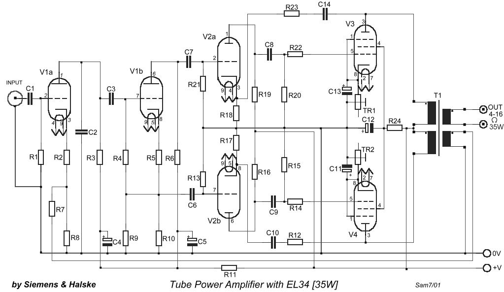
The circuit is designed to create a power amplifier that utilizes E80CC and EL34 vacuum tubes to achieve optimal performance, providing an output of 35 Watts. The power amplifier circuit employs E80CC and EL34 vacuum tubes, which are known for...
Dynamic microphones utilize a moving coil within a magnetic field to convert mechanical movements into electrical signals. An ordinary mini speaker can be transformed into a... Dynamic microphones operate on the principle of electromagnetic induction. When sound waves hit the diaphragm...