
mercury v8 monterey 1963 wiring diagram
The 1963 Mercury V8 Monterey wiring diagram is an essential tool for understanding the electrical system of this classic vehicle. The right side of the diagram illustrates critical components that facilitate the operation of various electrical functions.
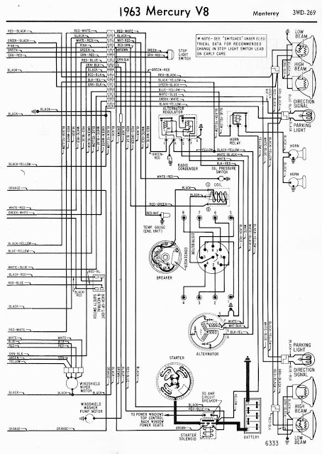
The low beam and high beam circuits are represented, indicating how the headlights are powered and controlled. The direction signal circuit is crucial for turn signal operation, ensuring that the vehicle's signaling system is functional and complies with road safety regulations. The parking light circuit is also included, highlighting its role in providing visibility when the vehicle is stationary.
Additional components such as the horn, which is vital for signaling other drivers, and the oil pressure switch are depicted, emphasizing their importance in engine monitoring and safety. The alternator regulator is illustrated, showing its function in managing the vehicle's electrical output and maintaining battery charge. The ignition coil is also represented, which is essential for the ignition system, converting low voltage from the battery into the high voltage needed to ignite the fuel-air mixture in the engine.
For effective assembly and troubleshooting, it is recommended to have a comprehensive understanding of both sides of the wiring diagrams. This ensures that all connections are correctly made and that any potential issues can be accurately diagnosed and resolved. The availability of these diagrams for free download allows enthusiasts and technicians to access necessary information conveniently, promoting safe and efficient maintenance of the 1963 Mercury V8 Monterey's electrical systems.Here is the 1963 Mercury V8 Monterey wiring diagram. This is the right side of the wiring diagrams, earlier, we have shown the Mercury V8 Monterey 1963 Wiring Diagram Left Side Part. This wiring diagram is very clear, and it shows a complete components and connections. Components you will see inside this right side wiring diagram are like: low bea m, high beam, direction signal, parking light, horn, oil pressure switch, alternator regulator, coil, etc. Be sure to read both sides of the wiring diagrams of the 1963 Mercury V8 Monterey first before performing any wiring work like assembly or troubleshooting in your cars wiring systems.
You can save these wiring diagrams for free in your PC. Work safe and have fun. 🔗 External reference
Related Circuits
The purpose of this timer is to disconnect the compressor circuit and connect a resistive heating element located near the evaporator at regular time intervals. The defrost heater is controlled by a thermostat and is used to melt any...
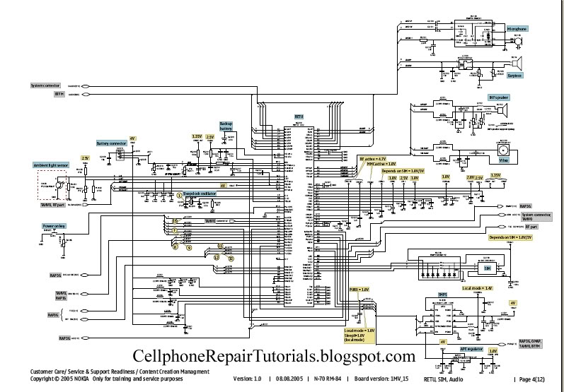
A schematic diagram is a layout of symbols and connections representing every electronic component in a circuit, serving as a guide to understanding how the circuit functions. Learning to read these diagrams may initially seem challenging, but it is...
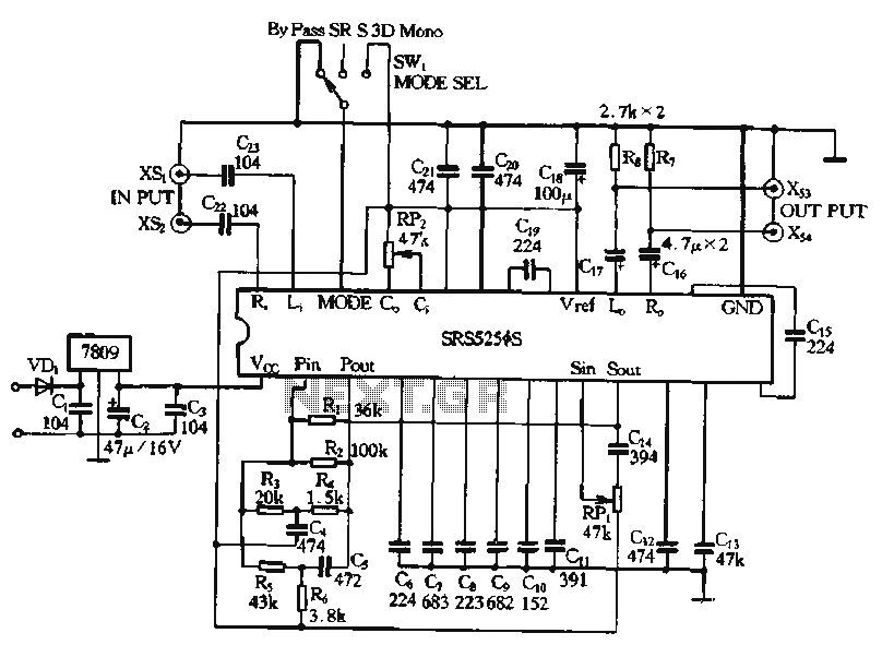
Typical application circuits for the Zheng brick SRS5250S are illustrated in the provided diagram. The SRS5250S features a pin diagram and a processing circuit that allows the user to switch between three operating modes: straight, SRS, and single-channel analog...
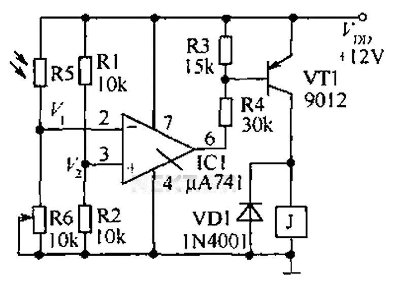
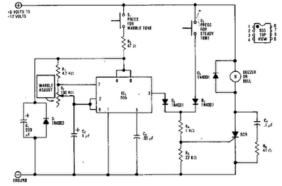
The circuit functions as a precision bright light control circuit, operating independently of variations in power supply voltage and ambient temperature. Resistors R1, R2, R6, and the photosensitive resistor R5 form a two-arm Wheatstone bridge. The precision bright light control...
The MT-2 Metal Zone™ is one of the most popular guitar pedals, delivering intense distortion tones characterized by pronounced mids and lows, along with an ultra-saturated sound. It features a distinctive dual-gain circuitry that enables long sustain and emphasizes...
Crystal 80mW FM transmitter circuit diagram of the production The Crystal 80mW FM transmitter circuit is designed to generate frequency modulated (FM) signals suitable for short-range audio transmission. This circuit primarily consists of a crystal oscillator, which serves as...