
Precision bright light control circuit diagram
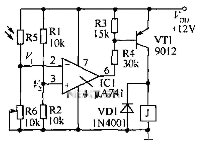
The precision bright light control circuit utilizes a Wheatstone bridge configuration to achieve stable performance under varying environmental conditions. The two-arm Wheatstone bridge, composed of resistors R1, R2, R6, and the photosensitive resistor R5, allows for precise measurement of light intensity.
In this configuration, R1 and R2 are fixed resistors, while R5, the photosensitive resistor, changes its resistance based on the ambient light level. R6 serves as a reference resistor. The balance of the bridge is affected by the resistance change of R5 as light levels fluctuate, which can be monitored through an output voltage signal.
This output can be used to control additional circuitry, such as dimming lights or activating alarms based on predefined light thresholds. The circuit's design ensures that it remains unaffected by variations in the power supply voltage, which is critical for maintaining consistent operation in different environments. Additionally, the compensation for ambient temperature changes allows for reliable performance across a range of conditions, making this circuit suitable for applications in both indoor and outdoor lighting control systems.
Overall, this precision bright light control circuit is an effective solution for applications requiring accurate light detection and control, ensuring optimal performance regardless of external factors. As shown in the circuit as a precision bright light control circuit, its work is not affected by the power supply voltage and ambient temperature. Resistors R1, R2, R6 and phot osensitive resistance R5 together constitute two-arm Wheatstone bridge.
Related Circuits

Below are three examples of controlling a relay from the PC's parallel printer port (LPT1 or LPT2). Figure A shows a solid-state relay controlled by one of the parallel port data lines (D0-D7) using a 300-ohm resistor and a...

This circuit diagram represents a DC voltage doubler and DC converter. It is designed to convert a 12V DC power supply into outputs of 24V DC and 18V DC. Nearly any PNP or NPN power transistors can be utilized...
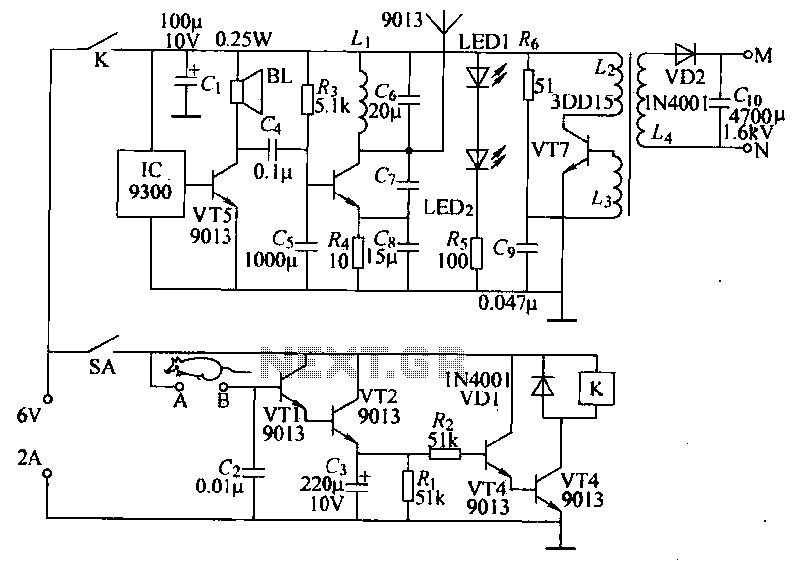
Power-saving electronic mousetrap. This example describes the minimal power consumption, which only occurs when a mouse enters the control zone during foraging activities. After a 30-second delay, the system enters a wait state, making it suitable for outdoor use....
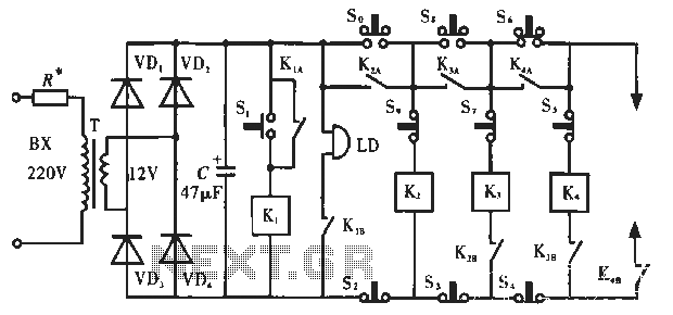
The circuit operates as illustrated in Figure 5-2a. It includes an alarm switch (S). When switch S is pressed, relay K is activated, which closes two normally open contacts. This action triggers the alarm bells. The alarm continues to...
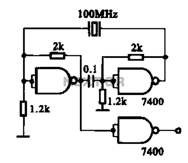
Crystal oscillator integrated circuits, specifically two diagrams of oscillator circuits with oscillation frequencies of 10 MHz and 20 MHz. Crystal oscillators are essential components in various electronic applications, providing stable frequency references for timing and synchronization purposes. The circuits presented...

A differential amplifier with input impedance as indicated in the circuit diagram. A differential amplifier is a crucial component in various electronic applications, primarily used to amplify the difference between two input voltages while rejecting any common-mode signals. This characteristic...