
How to Read Cellphones Schematic Diagrams
Page 2 includes a block diagram of the RF and baseband sections, which offers a fundamental overview of the circuit's connections. In telecommunications, baseband refers to signals and systems where the frequency range starts from zero up to a maximum bandwidth. This term is often synonymous with lowpass and contrasts with passband, bandpass, or radio frequency (RF) signals. RF encompasses oscillations within a frequency range of approximately 3 Hz to 300 GHz, which corresponds to the alternating current electrical signals used for radio wave production and detection.
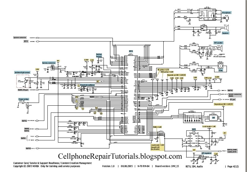
Page 3 illustrates the system connectors and components that interface with external elements, such as the headset, charger, and USB connections. Page 4 describes the power management circuit, audio codecs, drivers, and interfaces, including the microphone, earpiece, mouthpiece, vibrator, SIM card, and battery connections, which collectively represent the power supply area of the circuit. Page 6 details the section of the circuit responsible for processing applications, including the Flash IC and memory components where applications and firmware are stored. Finally, page 12 contains a table of all components mounted on the PCB, labeled with codes such as Rxxx for resistors, Cxxx for capacitors, and others.
Understanding these schematic diagrams is crucial for diagnosing and repairing hardware issues in mobile devices, allowing technicians to efficiently identify and resolve problems within the electronic circuitry. Each component's function, interconnections, and relationships can be thoroughly analyzed, enabling effective troubleshooting and repair strategies. Mastery of schematic reading not only enhances technical expertise but also empowers repair professionals to provide accurate solutions without dependency on external resources.Schematic Diagram is a layout of symbols and and connection of every electronic components circuit where serve as a guide on how the circuit function or work. Learn how to read it. At first you might think that it is hard to do so, You are not going to be an experts and master in cellphone repair as long as you don`t know how to read it.
Many amon g cellphone repairman exist nowadays that do not have any knowledge about reading it. They always rely on finding free solutions over the internet and forums. Those people who give free solutions are those people who knows how to read a schematic diagram. Now here`s your chance to learn and do not rely unto others, and be an expert and master troubleshooter when it comes to hardware problems. 1. You need to download service Schematic Diagrams, as many or complete package in every cellphone products.
each unit of a product have specific service diagrams. Now assuming that you already have those I`ve mention above; Let`s try to open up one file like for example we are going to open a schematic diagram of Nokia N70. B. page 2, In this page is a block diagram of an RF and Baseband: this is a basic explanation of the entire connection of a circuit.
It was called a block diagram for it is being drawed into blocks. In telecommunications and signal processing, baseband is an adjective that describes signals and systems whose range of frequencies is measured from zero to a maximum bandwidth or highest signal frequency; it is sometimes used as a noun for a band of frequencies starting at zero. It can often be considered as synonym to lowpass, and antonym to passband, bandpass or radio frequency (RF) signal.
Radio frequency (RF) is a frequency or rate of oscillation within the range of about 3 Hz to 300 GHz. This range corresponds to frequency of alternating current electrical signals used to produce and detect radio waves.
Since most of this range is beyond the vibration rate that most mechanical systems can respond to, RF usually refers to oscillations in electronics circuits. C. page 3, here we can find the system connectors and parts of the unit that correspond to the user or outer parts such us headset, charger and USB connection interfaces.
D. page 4, The power management circuit, audio codecs and drivers and the interfaces like the microphone, earpiece, mouthpiece, vibrator, sim-card, battery connections. This is the Power Supply Area of the entire circuits. F. page 6, This is the part of the circuit where the all application is being process, Flash IC and memories, this also where application and firmware are being stored.
L. page 12, This is where the table of each and every components is mounted on the PCB board written in codes, like Rxxx - resistorr, Cxxx - Capacitor and etc. 🔗 External reference
Related Circuits
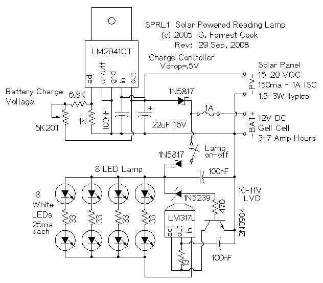
The reading lamp consists of a small solar panel, a standard UPS style lead acid battery, and an LED circuit board. The circuit board contains a low power solar charge controller (regulator), a set of 8 white LEDs, a...
Here is a 12 volt / 2 amp lamp dimmer that can be used to dim a standard 25 watt automobile brake or backup bulb by controlling the duty cycle of an astable 555 timer oscillator. When the wiper...
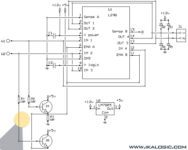
This implementation utilizes the L298 integrated circuit to drive motors and inductive loads with a continuous current capacity of up to 4A. The L298 consists of two independent channels, each capable of driving loads of up to 2A. By...
The LM3886 high-performance audio power amplifier circuit schematic is a crucial component in sound reproduction within audio systems. This audio power amplifier utilizes the LM3886 integrated circuit to enhance sound quality and output. The LM3886 is a high-performance audio power...
Craftsman Garage Door Opener Schematic and Installation Manuals. Sears Craftsman Garage Door Opener Parts. With 15 years in the business, Garage Door Openers Superstore is a leading provider. The schematic for the Craftsman Garage Door Opener provides a comprehensive overview...
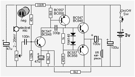
The following circuit presents a Mini Audio Amplifier Circuit Schematic Diagram. Features include a power consumption of less than 3mA, a small output, and the use of a push-pull configuration. The Mini Audio Amplifier Circuit is designed to amplify low-level...
Warning: include(partials/cookie-banner.php): Failed to open stream: Permission denied in /var/www/html/nextgr/view-circuit.php on line 713
Warning: include(): Failed opening 'partials/cookie-banner.php' for inclusion (include_path='.:/usr/share/php') in /var/www/html/nextgr/view-circuit.php on line 713