
Metal detector circuit diagram 1
The metal detector circuit is designed to identify metallic objects by employing a variety of electronic components that work together to generate and process signals. The fixed frequency oscillator produces a stable frequency output, which is essential for the detection process. The ceramic filter (ZC) ensures that only specific frequency ranges are passed through, while the transistor (V1) amplifies the signal. Resistors (R1 to R4) and capacitor (C2) are used to set the operating point and filter the output, respectively.
The mixer component, utilizing mixer tube (V2), combines the output from the fixed frequency oscillator with the detection oscillator's signal. Capacitor (C3) and resistors (R5 to R8) are utilized to condition the signals for optimal mixing, ensuring that the resulting signal contains the necessary frequency components for detection.
The detector section is critical, as it converts the mixed signals into a form that can be analyzed for the presence of metals. Diodes (VD1, VD2) rectify the signal, while capacitors (C8 to C12) and resistor (R12) smooth and filter the output. The potentiometer (RP) allows for sensitivity adjustments, enabling the user to fine-tune the detector's response to different metal types and sizes.
The detection oscillator generates a signal that varies with the presence of metallic objects, utilizing transistor (V3), inductance coil (L), capacitors (C4 to C7, C19), and resistors (R9 to R11) to form a feedback loop that enhances the detection capability. This section is vital for differentiating between various types of metals based on their unique electromagnetic responses.
Finally, the audio amplifier section converts the detected signals into audible sounds. The power amplifier integrated circuit (IC) drives the speaker (BL) with sufficient power, while resistors (R13 to R15) and capacitors (C13 to C18) are used to filter and amplify the audio signals, ensuring clear sound output for the user.
Overall, the metal detector circuit is a complex assembly of components that work in tandem to effectively detect metallic objects, making it a valuable tool for various applications, including treasure hunting and security screening.The metal detector circuit consists of the fixed frequency oscillator, mixer, detector, detection oscillator and power amplifier circuit, and the circuit is shown as the chart. Fixed frequency oscillator circuit consists of ceramic filter ZC, transistor VI and resistors R1 ~ R4, capacitor C2 and so on.
Mixer consists of the mixer tube V2 and capac itor C3, resistors R5 ~ R8. Detector is composed of the diodes VD1, VD2, capacitors C8 ~ C12 and resistor R12, potentiometer RP and other components. Detection oscillator is composed of the transistor V3, inductance coil L, capacitors C4 ~ C7, C19 and resistors R9 ~ R11.
Audio amplifier is composed of power amplifier integrated circuit IC, resistors R13 ~ R15, capacitors C13 ~ C18 and speaker BL. 🔗 External reference
Related Circuits
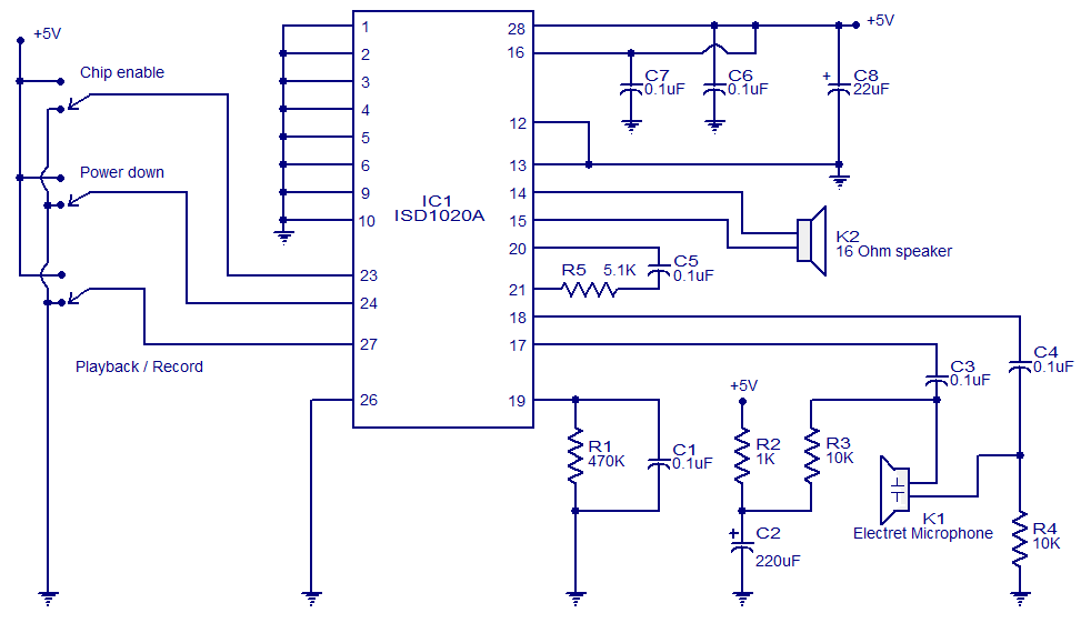
This circuit is designed in response to a request made by Mr. Vignesh for a voice recording and playback system. The circuit utilizes the ISD1020A IC from ISD, which is a CMOS single-chip record/playback device capable of recording voice...

This is a simple smoke alarm circuit using a timer IC, the NE555. The circuit operates by illuminating a Light Dependent Resistor (LDR) with a lamp. When smoke obscures the light from the lamp, the resistance of the LDR...
A DC-to-DC step-up converter is typically implemented using a transformer, which converts DC voltage to AC voltage, steps it up with the transformer, and then rectifies and filters the output to achieve a higher DC voltage. However, a voltage...
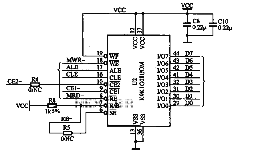
This document illustrates the application of the MP3 player memory chip ACU7505 within a clamor circuit, designed to support the overall machine CPU and MP3 decoder core. The chip is utilized to address high data storage capacity requirements, implemented...
This microphone preamplifier utilizes the low-noise integrated circuit (IC) uA739. It serves as a practical example of designing an effective preamplifier for dynamic microphones. The IC contains two identical integrated preamplifier circuits, with the second preamp functioning in the...
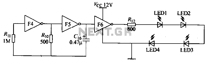
Gates F4, F5, and F6 together form a low-frequency oscillator that drives high-brightness light-emitting diode (LED) flashes. The light-emitting diodes may be arranged around the booth seat for decorative purposes. The automatic referral machine is used prior to operation...