
Low frequency oscillation circuit
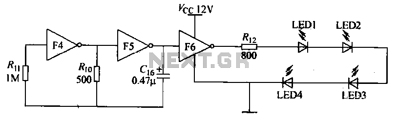
The circuit described involves a combination of gates and components that facilitate the functionality of a low-frequency oscillator, which is essential for generating the flashing signals for the high-brightness LEDs. The arrangement of LEDs around the booth seat enhances visual appeal, making the setup suitable for various applications, such as exhibitions or displays.
The K2i button serves as a trigger for initiating audio recording. When pressed, it activates the recording circuit, which includes a microphone and an audio processor. This processor captures the user's voice and converts it into a digital format for storage. The feedback provided by the initial "beep" indicates that the recording is active, ensuring that users are aware of the operational status.
Upon completion of the voice recording, the S2 button is utilized to finalize the recording session. The subsequent "beep" from the speaker serves as an audible cue that the recording has ended successfully. In scenarios where the recording exceeds the allowed duration, the circuit is designed to emit warning beeps, thus preventing unintended extensions of the recording time. This feature is crucial for maintaining the integrity of the recorded message and ensuring that it fits within the designated playback parameters.
The S1 button is pivotal in providing user control over the playback of the recorded message. By pressing this button, the user can stop the audio output at any moment, allowing for flexibility during presentations. This functionality is particularly beneficial in dynamic environments where user interaction is essential.
Overall, the integration of these components within the circuit not only enhances user experience but also ensures that the device operates efficiently, providing both visual and auditory stimuli that can be tailored to specific needs. The design considerations reflect a balance between functionality and user interface, making the circuit suitable for a variety of applications in decorative and informative settings.Gate F4, F5, F6 together form a low frequency oscillator, driving high brightness light-emitting diode flashes, light emitting diodes may be arranged around the booth seat, play a decorative role. (4) use of goods automatic referral Shao machine prior to use pre-recorded, recording K2i then press and hold the speaker will issue a "beep" beep tone, then toward the microphone for recording. The voice recording product presentation prepared after completion of release S2, the speaker will then issue a "beep" is heard, indicating the end of recording, if the recording time exceeds the time allowed by the chip, when the sheet reaches Cang allow time will be issued a "tick, tick "beep twice forced to end recording.
S1 is the stop button, the machine language product description describes the sound as long as the answer it when you can stop Sl voice introduction.
Related Circuits
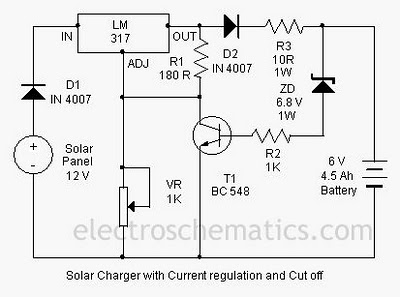
A solar charger circuit is designed to charge lead-acid batteries or nickel-cadmium (Ni-Cd) batteries using solar power. This circuit captures solar energy to charge a 6-volt, 4.5 Ah battery for various applications. It features voltage and current regulation along...
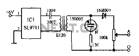
The electronic frostbite treatment instrument ASIC SL9711 consists of an oscillation circuit, a power amplifier, and a controller. It generates a sine wave at frequencies of 100 Hz and 3 Hz, followed by a step-up transformer with potentiometer adjustment...

The circuit consists of a relaxation oscillator created by Q1 and an SCR flip-flop formed by Q2 and Q3. When the supply voltage is applied to the circuit, the timing capacitor C1 charges to the firing point of the...

This circuit ensures that a blinking slowly, ie the lamp is brighter lights until a maximum is reached and then gradually decrease in strength until the lamp is off. IC1a opamp is used here to a triangular voltage generation....
The wireless FM transmitter circuit described here includes an additional RF power amplifier stage following the oscillator stage, which increases the power output to 200-250 mW. The wireless FM transmitter circuit functions by modulating audio signals onto a radio frequency...
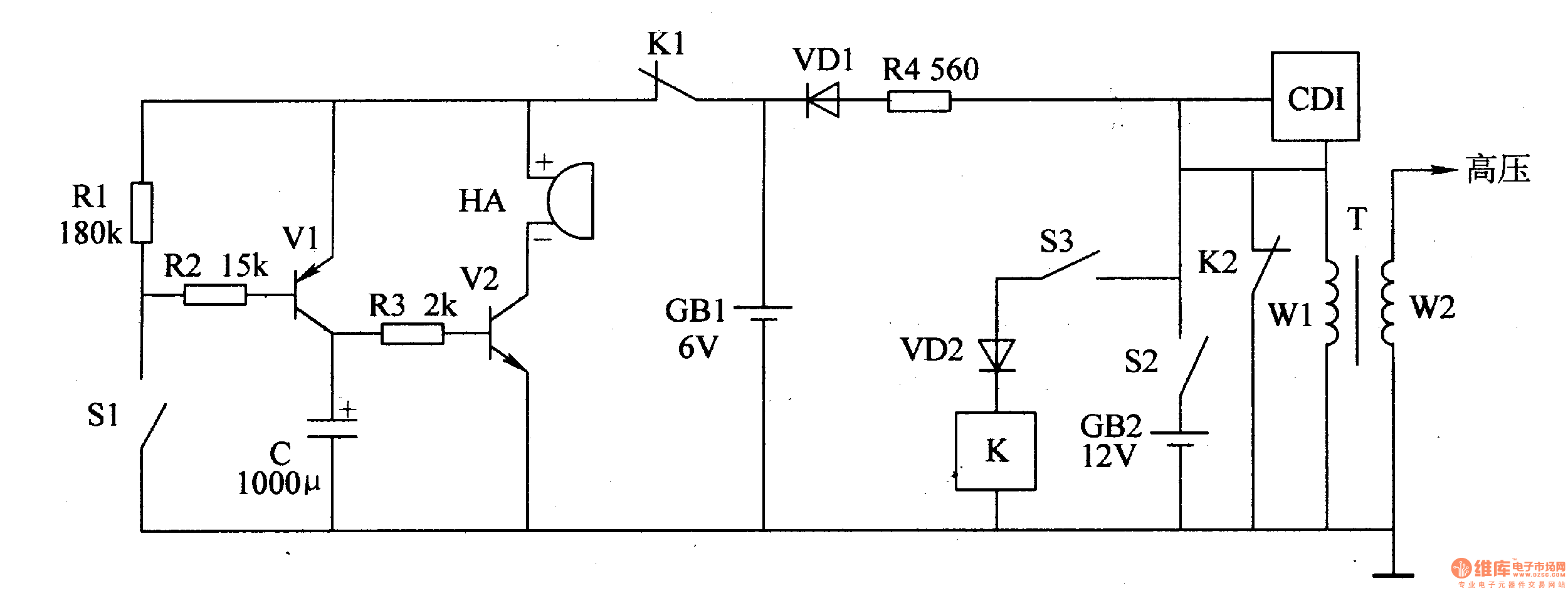
The motorcycle anti-theft alarm circuit consists of a detection alarm circuit, a charging circuit, and an anti-theft control circuit, as illustrated in figure 7-94. The detection alarm circuit includes a mercury switch (S1), resistors (R1-R3), a capacitor (C), transistors...