
Metal detector circuit diagram 2
The metal detector circuit operates by utilizing a combination of oscillation and amplification techniques to detect metallic objects. The power circuit supplies the necessary voltage and current, powered by batteries GBI and GB2, while filter capacitors C1 and C2 ensure a stable power supply by smoothing out any fluctuations. The power switch allows for the activation or deactivation of the entire circuit.
The sine wave oscillator generates a continuous sine wave signal, which is essential for the detection process. Transistor VI is responsible for amplifying the signal produced by the detecting coil (L), which is the primary sensor element of the metal detector. Capacitors C3 to C5 and resistors R1 and R2 are configured to set the frequency and stability of the oscillator.
The PLL circuit plays a crucial role in maintaining a consistent frequency for the detection process. This circuit includes a dual time-base integrated circuit that helps synchronize the output frequency with the incoming signals from the detecting coil. Resistors R3 and the adjustable potentiometer RP1 allow for fine-tuning of the phase-locked loop, while capacitors C6 to C8 stabilize the circuit's performance.
The hybrid amplifying circuit enhances the overall sensitivity of the metal detector. Transistors V2 and V3 amplify the detected signals, ensuring that even small metallic objects can be identified. Resistors R4 to R6 and potentiometer RP2 are used to adjust the gain of the amplifying stage, while the ammeter PA provides a visual indication of the signal strength.
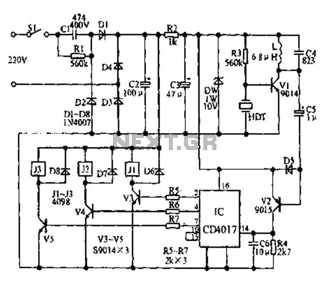
Overall, this metal detector circuit combines various electronic components to create an effective and sensitive detection system, suitable for various applications in locating metallic objects. The use of carbon film resistors rated at 1/4W or 1/8W ensures reliability and precision in the circuit's operation.The metal detector circuit is composed of the power circuit, sine wave oscillator, PLL phase-locked loop circuit and hybrid amplifying circuit, and the circuit is shown as the chart. Power circuit is composed of the batteries GBI, GB2, filter capacitors C1, C2, and the power switch s (Sa, Sb).
Sine oscillator circuit consists of transistor VI, det ecting coil L, capacitors C3 ~ C5 and resistors RI, R2. PLL phase-locked loop circuit IC consists of dual time-base integrated circuit and resistos R3, potentiometer RP1, capacitors C6 ~ C8. Hybrid amplifying circuit is composed of the transistors V2, V3, resistors R4 ~ R6, potentiometer RP2 and ammeter PA.
R1 ~ R6 use l/4W or l/8W carbon film resistors. 🔗 External reference
Related Circuits
Any ideas? Is this circuit going to be standalone? Is there any other circuitry around it, perhaps a microcontroller? What circuitry does the timing device contain, or does it even contain electronics? Abdullah Kahraman Mar 22, '13 at 18:10....
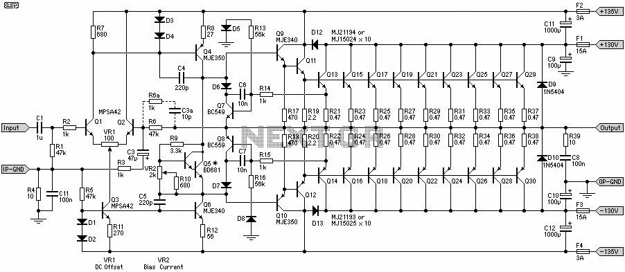
This 1500W Power Amplifier Circuit Diagram contains two images of the circuit. For more complete information, refer to the main post titled "1500 Watt Power Amplifier." It includes a list of component parts for the 1500W Power Amplifier Circuit...
Fans can be controlled remotely with a switch that allows for speed adjustments, and this remote control can also be integrated with other household switches. Its primary feature is the use of a sub-transmission ultrasonic transmitter, which operates without...
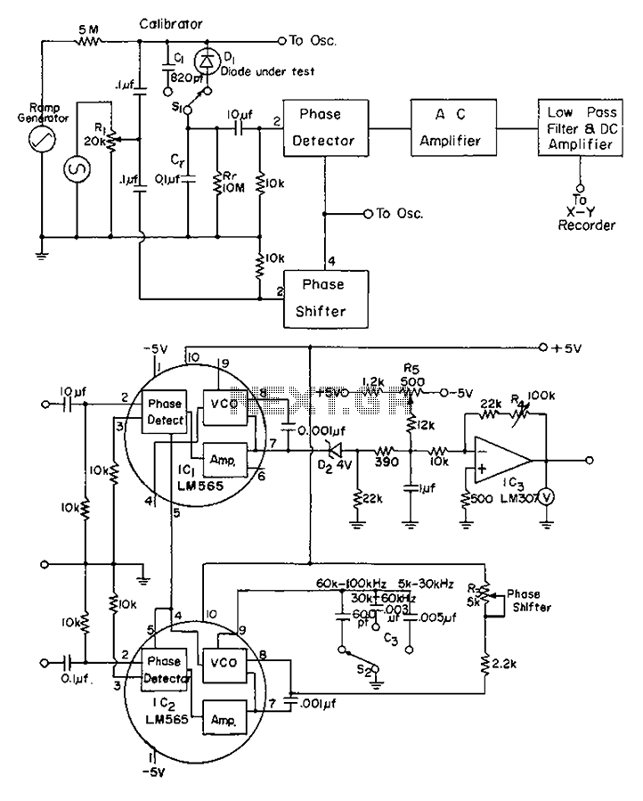
The application of automatic plotters for measuring the capacitance-voltage characteristics of solar Schottky gate diodes is discussed. A diode is connected as illustrated below. The integrated circuit (IC) generates a square wave output phase. Additionally, resistor R3 can be...
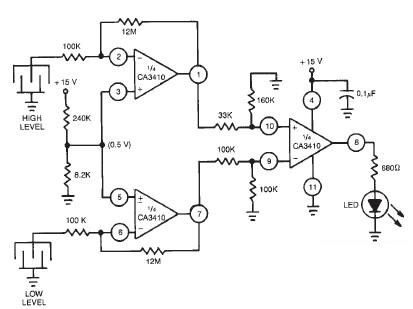
This liquid level sensor electronic circuit diagram utilizes a common CA3410 operational amplifier integrated circuit (IC). The sensor employs two plate sensors (or probes), one designated for detecting high liquid levels and the other for low liquid levels. If...
This document contains a collection of various useful and interesting electronic schematics. Some of these schematics are referenced or included in other documents on this site. Notably absent from this collection is extremely important safety information, which can be...
Warning: include(partials/cookie-banner.php): Failed to open stream: Permission denied in /var/www/html/nextgr/view-circuit.php on line 713
Warning: include(): Failed opening 'partials/cookie-banner.php' for inclusion (include_path='.:/usr/share/php') in /var/www/html/nextgr/view-circuit.php on line 713