
1500W Power Amplifier Circuit
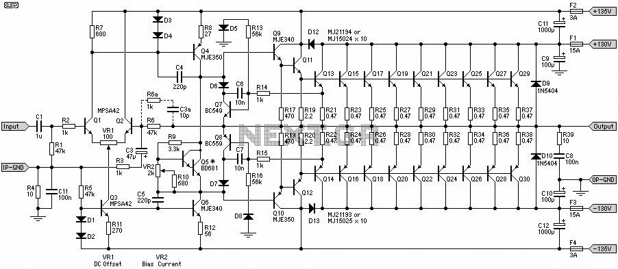
The 1500W Power Amplifier circuit is designed for high-performance audio amplification, making it suitable for professional audio applications. The circuit utilizes a robust configuration of 10 pairs of power transistors, which are essential for delivering high current and voltage output. The choice of transistors, such as MJ15024 and MJ15025, or MJ21193 and MJ21194, ensures that the amplifier can handle the thermal and electrical demands of high-power operation.
The circuit layout typically includes a differential input stage, which is responsible for amplifying the input audio signal. Following the input stage, the signal is processed through various amplification stages, ultimately driving the output stage composed of the aforementioned power transistors. These transistors are configured in a push-pull arrangement to maximize efficiency and minimize distortion.
To power this amplifier, a dual output power supply providing 130V is necessary. This high voltage supply is critical for achieving the desired output power levels without clipping or distortion, especially at high volumes. Proper heat dissipation mechanisms, such as heat sinks and possibly fans, should be implemented to maintain optimal operating temperatures for the transistors during prolonged use.
The circuit design also incorporates feedback mechanisms to enhance linearity and reduce harmonic distortion, contributing to a cleaner audio output. The overall design should be carefully implemented on a printed circuit board (PCB) to ensure stability and reliability, with attention paid to the layout to minimize noise and interference.
In summary, the 1500W Power Amplifier Circuit Diagram serves as a comprehensive guide for building a high-power audio amplifier, with detailed information on component selection, circuit configuration, and power requirements. This amplifier is suitable for users seeking high fidelity and substantial power output in audio applications.This 1500W Power Amplifier Circuit Diagram was contain 2 image(s) circuit. More complete of the post content, you can read carefully at the main post content of this image titled 1500 Watt Power Amplifier. Just click here and jump directly to the main post content. Not only the circuit information, at the 1500 Watt Power Amplifier you also can find the list of component part for 1500W Power Amplifier Circuit Diagram The image above was tagged in Power Amplifier, Audio Amplifier schematic, . Tagged together with Audio Amplifier, 1500 Watt Power Amplifier Diagram, Power Amplifier Diagram, . Tagged together with 1500 Watt Power Amplifier, 1500 Watt Power Amplifier Circuit, Power Amplifier Circuit, .
Tagged together with Amplifier, also uploaded by TB in December 04th, 2011. FYI image above, also we serve for you a few other posts which we think its related also have a similar term with this post. We give you additional related post below. Or, for other choises, you can find the similar post which have the same tags or labels. Do not confused to find the same term, you just clicks the links belows, we ease you too see what you looking for.
Do not forget to get our latest information from us. We suggest for keep an eye in facebook, twitter, or subscribe with RSS feed. With that, we guaranted you will get faster information about our latest post at the same time we post the article. Our engine was automatically calculate and noted that image of 1500 Watt Power Amplifier has been viewed by 254 user since we published the post on December 04th, 2011.
And from the number of visitors, about 169 user has download this image. In addition, we also detects that there are already 104 user who have been willing to give a rating on the 1500W Power Amplifier Circuit Diagram. Very high power amplifier with 10 pairs of power transistor. Can use MJ15024 and MJ15025 or MJ21193 and MJ21194. Those 20 pieces transistor work as final active component for final gain. This circuit required dual output power supply 130V. 1500 Watt Power Amplifier Labels: Power Amplifier Audio Amplifier schematic Audio Amplifier 1500 Watt Power Amplifier Diagram Power Amplifier Diagram 1500 Watt Power Amplifier 1500 Watt Power Amplifier Circuit Power Amplifier Circuit Amplifier Article: 1500 Watt Power AmplifierCategory: AmplifierImage Uploaded: 2Image Format: jpg - gifFull Size Image Dimention: 902 x 393 pixelsCurrent Size Dimention: 902 x 393 pixelsAuthor: TBDate: December 04th, 2011Time: 18:59:01 PMSource (via):
🔗 External reference
Related Circuits
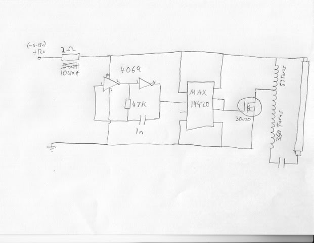
The lighting hood of the AquaOne AR-320 tank typically comes with low-quality tubes that have inadequate power output and a color spectrum conducive to algae growth. Various improvement methods exist, such as replacing the hood with a metal halide...
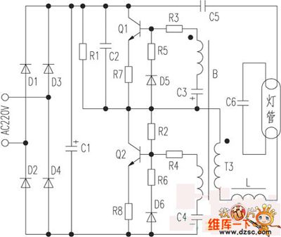
The saving lamp circuit features two main types: glass cover and exposed. The glass cover variants include three series: spherical, cylindrical, and processing types. The first two series consist of four variations: transparent, carved, engraved, and white. These lamps...
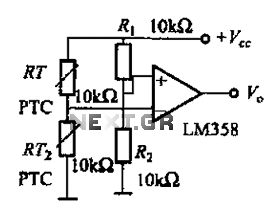
The basic application circuit for a thermistor is illustrated. Figure (a) depicts a fundamental temperature measurement circuit with limited accuracy, suitable only for applications that do not require high precision. RT represents a positive temperature coefficient thermistor; as the...
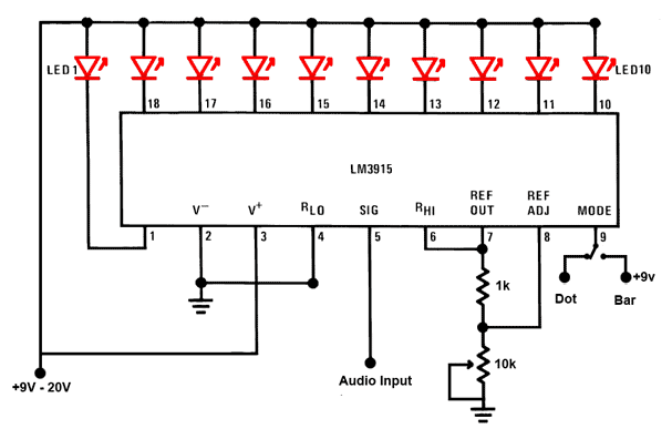
This is a simple audio sound level LED display circuit diagram. The circuit is entirely based on a single integrated circuit, the LM3915 from National Semiconductor. The LM3915 is a monolithic integrated circuit that displays the audio sound level...
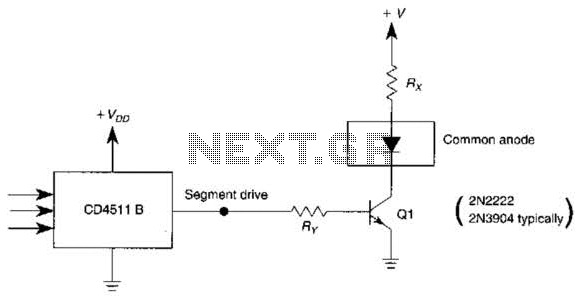
The use of a switching transistor, such as a 2N2222 or 2N3904, enables the operation of the CD4511B with a common-anode display. The transistor should be selected to provide approximately 1 mA to drive Q1, while resistor Rr must...
The presented design features an unconventional arrangement that provides certain advantages compared to traditional designs. To begin with, a linear power supply incorporates a transformer that steps down the line voltage to a level higher than the regulated output...
Warning: include(partials/cookie-banner.php): Failed to open stream: Permission denied in /var/www/html/nextgr/view-circuit.php on line 713
Warning: include(): Failed opening 'partials/cookie-banner.php' for inclusion (include_path='.:/usr/share/php') in /var/www/html/nextgr/view-circuit.php on line 713