
Metal Detector Circuit with Diagram and Schematic

The metal detector circuit utilizes a single transistor in conjunction with a radio receiver to detect the presence of metallic objects. The core of this design is based on the Colpitts oscillator, which is known for its simplicity and effectiveness in generating oscillations at radio frequencies.
In this schematic, the transistor acts as the main amplifying component, forming the oscillator circuit with the inclusion of capacitors and an inductor, which are essential for determining the oscillation frequency. The Colpitts configuration employs two capacitors in series with an inductor, creating a resonant tank circuit. This tank circuit resonates at a specific frequency that can be tuned to detect various metal types based on their conductive properties.
When a metallic object comes into proximity of the detector, it alters the inductance of the coil, resulting in a change in the frequency of oscillation. This frequency shift can be detected by the radio receiver, which is tuned to the oscillator's frequency. A simple audio output can be generated, indicating the presence of metal.
The circuit requires a power supply, typically a battery, which powers the transistor and the radio. Careful selection of the transistor is crucial, as it must have sufficient gain to amplify the weak signals generated by the oscillator. Additionally, the choice of the inductor and capacitors will affect the sensitivity and range of the metal detector.
Overall, this metal detector project exemplifies a practical application of basic electronic components and principles, making it an excellent choice for educational purposes or hobbyist experimentation.A simple metal detector circuit diagram and schematic using a single transistor and a radio. This metal detector/sensor project is easy to make and is an application of Colpitts oscillator.. 🔗 External reference
Related Circuits

The circuit utilizes a standard telephone ringing circuit, KA2401, along with additional components to control lighting in response to a ringing signal. The light control circuit can be activated externally by AC when the ringing signal is received. The...

A hoist rated at 22kW and below is equipped with a power-saving Y-conversion circuit, as depicted in the figure. This circuit enhances the standard hoist design by incorporating a CJ20-10A exchange contactor. The implementation of the Y-conversion circuit during...
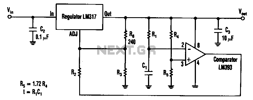
The timed two-voltage circuit can start and run a small DC motor or solenoid. The input voltage to the LM317 three-terminal regulator ranges from 5 to 40 V, and the output voltage can range from 2 to 36 V....

The TDA8358J application circuit is designed for television signal processing. The input signals are connected to the TDA8358J at pins 1 and 2, where pin 1 receives a positive sawtooth voltage input and pin 2 receives a negative sawtooth...

The detector is a bit more complex. It amplifies a microphone and sends the resulting signal to an NE567 tone decoder. The amplifier is half of a 1458 opamp. The two 120K resistors attached to pin 3 keep the...
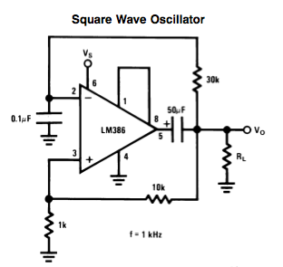
Here is a small LM386-based square-wave oscillator constructed from the following schematic. A 50k potentiometer was used in place of a 30k resistor, which functions as a pitch controller. The audio provided consists of track recordings made in Ableton...