
Light control circuit diagram

The described circuit effectively integrates a telephone ringing signal with a light control mechanism, employing the KA2401 as the core component. The KA2401 is a specific integrated circuit designed to generate ringing signals for telecommunication applications. It provides dual output signals that can be utilized to trigger other electronic components within the circuit.
The operation of the light control circuit hinges on the behavior of the photodiode (3DU). During the day, when ambient light levels are high, the photodiode exhibits low resistance, allowing for sufficient current flow to activate the thyristor (SCR). This activation results in a pronounced ringing sound, suitable for daytime conditions when background noise may mask quieter signals.
In contrast, the circuit is designed to adapt to nighttime conditions. As the light diminishes, the resistance of the photodiode increases significantly, which alters the functioning of the circuit. The higher resistance limits the current that can flow through the thyristor, thereby reducing the overall ringing signal. This is further influenced by the presence of resistor R2, which acts to attenuate the ringing signal even more, ensuring that it remains subtle and less intrusive during nighttime hours.
The implementation of this circuit is advantageous in environments where it is necessary to manage sound levels based on the time of day, providing a practical solution for residential or commercial applications. The use of the KA2401 in conjunction with the photodiode and thyristor creates a responsive system that balances functionality with user comfort.Use of ordinary telephone ringing circuit KA2401 and peripheral components, the installation of the light control when the bell simply access in the country (a) the "X" at the country (b), the light control circuit can be: external AC when the ringing signal input, KA2401 two 8-pin output signal ringing tone, if during the day, photodiodes 3DU resistance is small, the thyristor SCR turns on, ringing larger; if no light at night, 3DU resistance is (number Meg), only through the ringing signal attenuation by R2, ringing much smaller.
Related Circuits
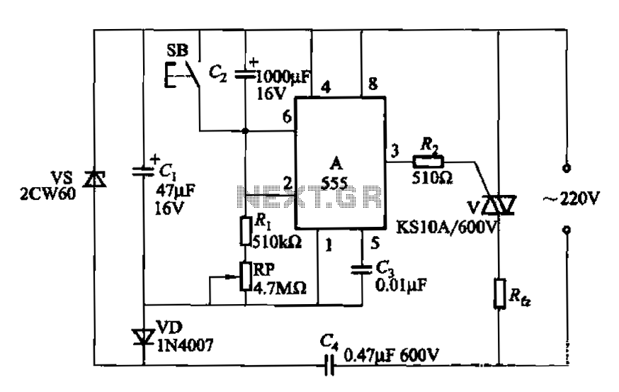
The circuit utilizes a 555 Integrated Circuit (IC) configured as a delay circuit. It transitions from a low to a high state after a button (SB) is pressed, initiating a delay before the output terminal goes high. The output...
This circuit resembles an LED clock but utilizes 12 neon indicator lamps in place of LEDs. It operates on two high-capacity nickel-cadmium cells (2.5 volts), providing power for several weeks. A small switching power supply generates the high voltage...
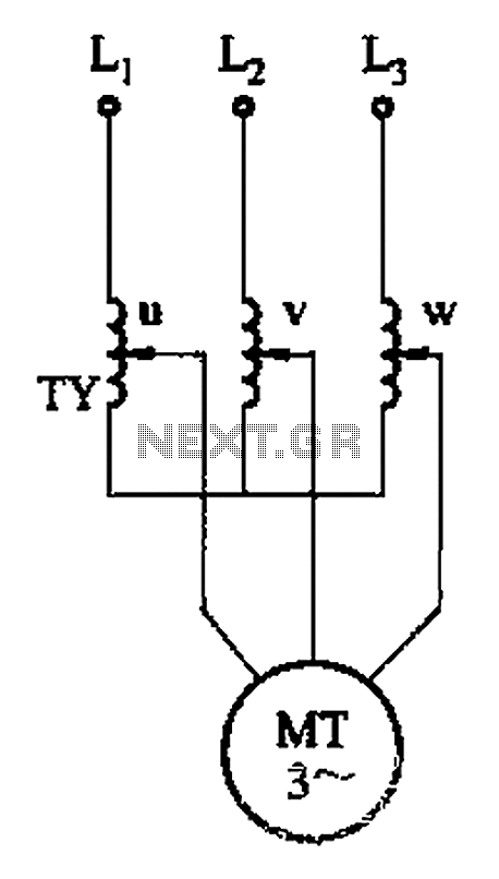
The circuit depicted in Figure 3-176 illustrates an adjustment method that allows the motor to operate at equilibrium. The adjustment range is relatively wide; however, it necessitates a three-phase voltage regulator, which incurs higher input costs. The circuit design in...
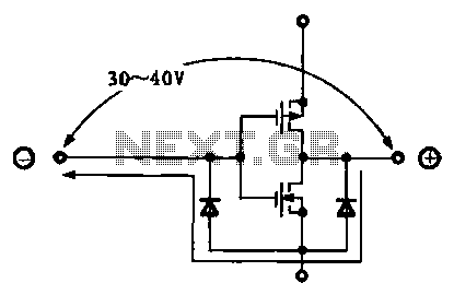
Due to the varying conditions of different input signals, when an abnormal voltage is applied to the pin, protection circuits are designed to create a circuit path that secures the internal protection of large-scale integration (LSI) circuits. The structure...
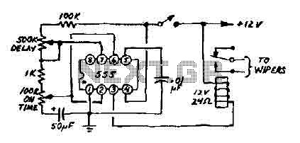
This 12V wiper speed controller circuit utilizes a 555 timer. It is a straightforward and practical circuit that can be installed in any car. The 12V wiper speed controller circuit is designed to regulate the speed of windshield wipers in...
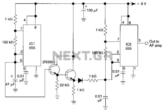
The ramp voltage from the low-frequency oscillator IC1 modulates IC2, thereby producing a rising and falling tone similar to the wail of police cars. The described circuit utilizes a low-frequency oscillator (IC1) to generate a ramp voltage. This ramp voltage...