
TDA8358J application circuit

The TDA8358J is a highly integrated circuit designed for television applications, particularly for horizontal and vertical deflection control. In this circuit, the positive and negative sawtooth voltages applied to pins 1 and 2, respectively, are critical for generating the necessary deflection signals. The differential amplifier within the TDA8358J processes these input signals, allowing for precise control over the output waveform.
The push-pull power amplifier configuration is essential for driving the deflection coil, which is responsible for the movement of the electron beam in CRT televisions. The output from the power amplifier is applied to the deflection coil connected to pins 10 and 4, facilitating the horizontal and vertical scanning of the display.
The resistor RM serves a dual purpose: it limits the current through the deflection coil and provides feedback to enhance the linearity of the sawtooth waveform. This feedback mechanism is crucial for maintaining the accuracy of the deflection signals, ensuring that the displayed image remains stable and free from distortion. The feedback voltage at pin 12 (Rs) is a vital component of this feedback loop, allowing for dynamic adjustments to the output characteristics.
To optimize performance, the values of RM and RCV can be adjusted to tailor the circuit's response to specific requirements. However, it is imperative to ensure that the output current remains below the specified limit of 3.2 A peak-to-peak to prevent damage to the circuit components and maintain reliable operation. Proper selection of these resistors will help achieve the desired output current while maximizing the dynamic range and linearity of the deflection signals, ultimately resulting in improved image quality on the display. As shown for the TDA8358J actual application circuit. Television signal processing circuit input signals are input TDA8358J Hill 1,2 feet, positive sawtooth voltage input pin 1 , pin 2 negative sawtooth voltage input. After an internal signal of the differential amplifier and push-pull power amplifier output is applied to the deflection 10,4 feet across the coil. RM resistor in series with the deflection coil, providing feedback voltage by Rs 12-pin input, the linear sawtooth output is improved, and expanded dynamic range with a sawtooth wave.
Adjusting the resistance RM and RCV can change the output current, the output current must not exceed 3.2Ap-p.
Related Circuits
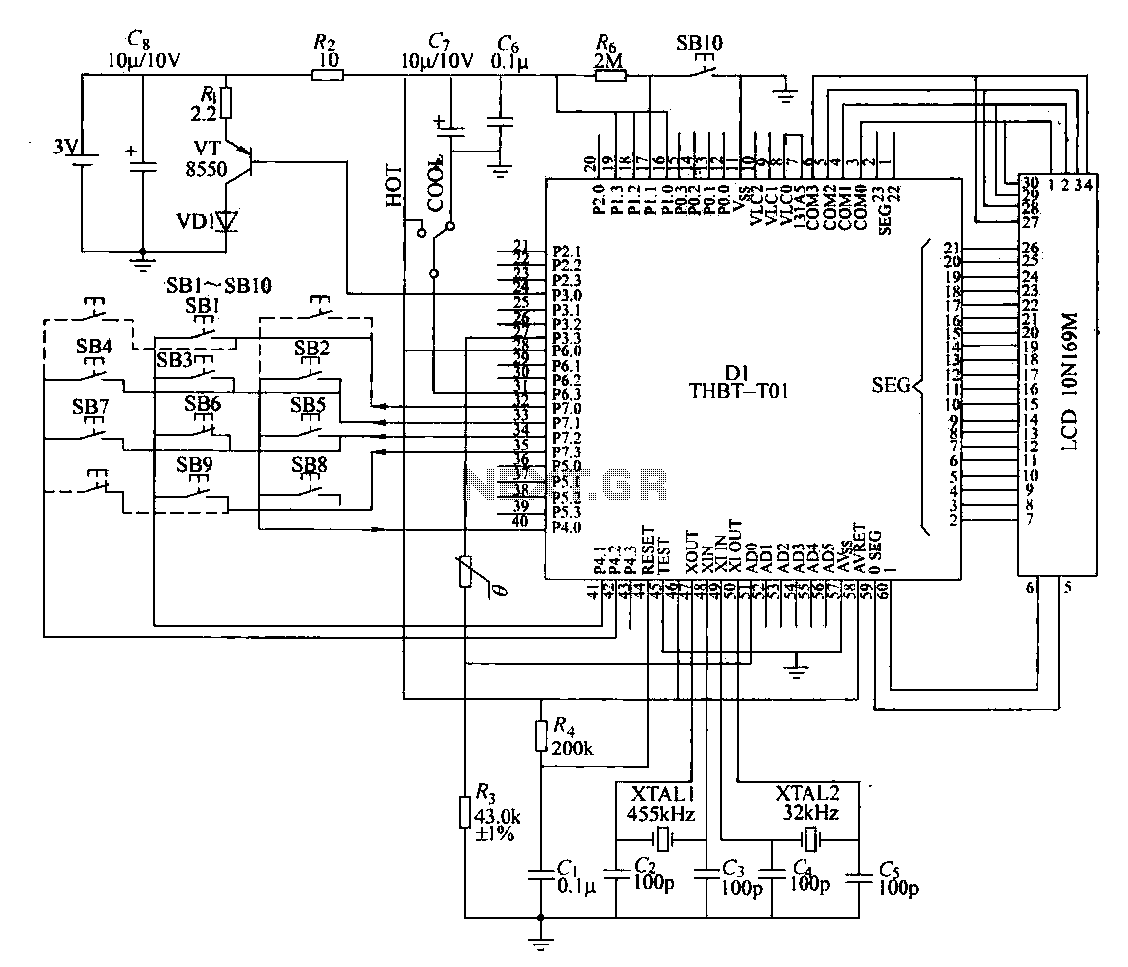
The circuit composition of a specific remote control transmitter is illustrated in a diagram. The transmitter primarily consists of a large-scale integrated circuit chip (D1, THBT-T01), a 4.5 kHz crystal oscillator, a 32 kHz crystal oscillator, a liquid crystal...
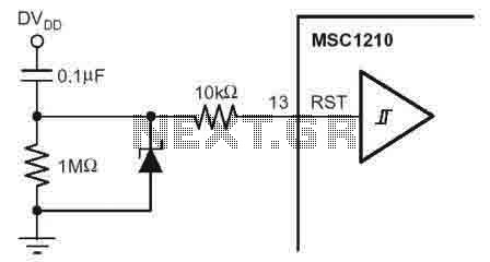
According to the MSC1210 datasheet, you will perform an external reset by taking RST pin high for two tOSC periods as this stops device operation, crystal oscillation, causes all digital pins to be pulled high from that point and...
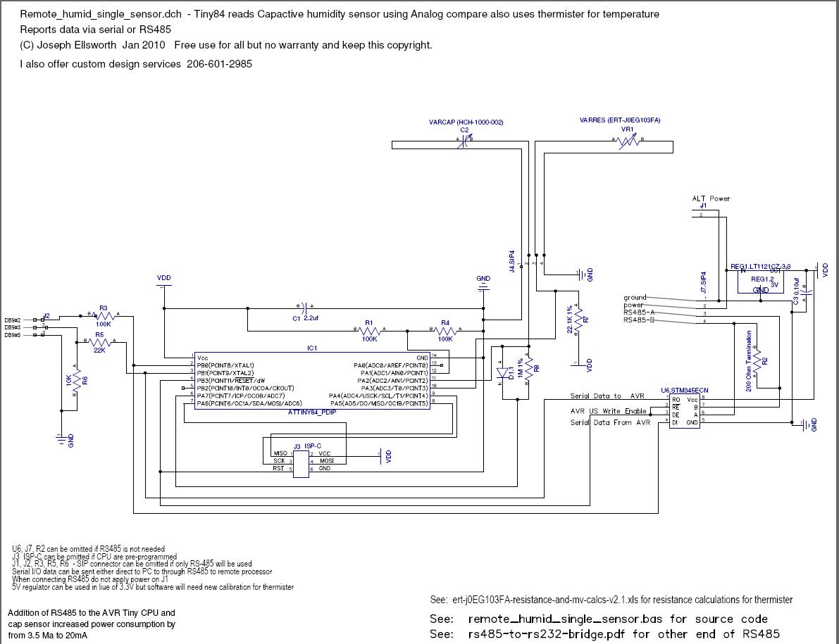
This document explains how to read a capacitive humidity sensor directly from a microcontroller using one resistor, one diode, the sensor, and two I/O lines. This method does not use an ADC but measures the time required to charge...
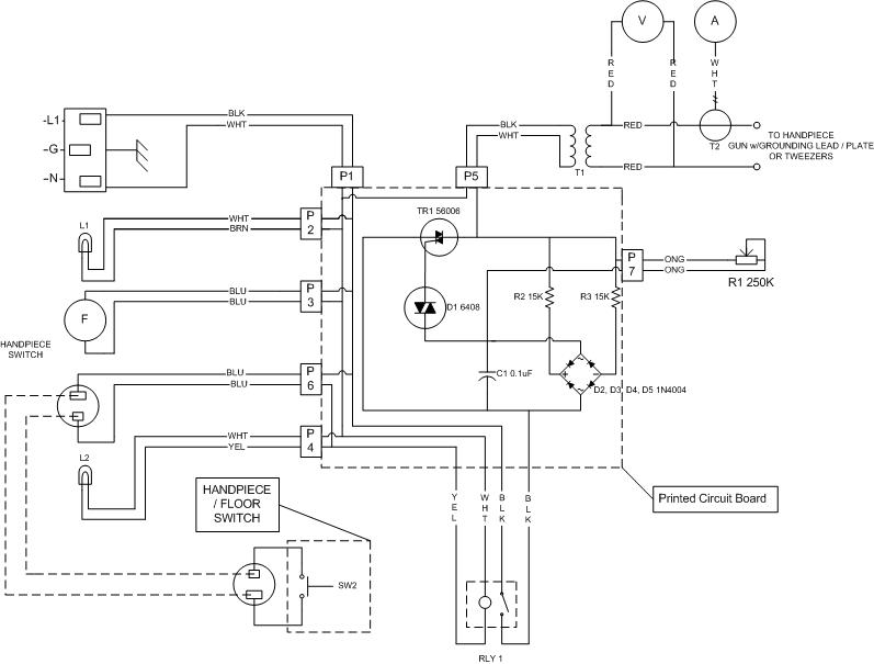
The most challenging aspect of the build was to find or design a circuit capable of handling the load while remaining within budget. This circuit achieves both objectives. It adjusts the power output using a potentiometer (variable resistor) R1,...
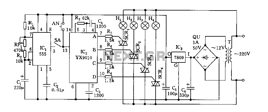
Fantasy lights offer wonderful changes suitable for storage, dance halls, or family holiday decorations. The control circuit is depicted here, which includes a multivibrator control circuit, a thyristor trigger circuit, and a step-down power supply circuit. The AC step-down...
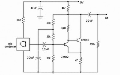
Preamp circuits are used in front of an RF oscillator to create an RF transmitter that is highly sensitive to sound. A microphone preamp must provide stable gain. Preamp circuits play a crucial role in the functioning of RF transmitters...