
Meter check of a diode

Using an ohmmeter to check a diode presents a limitation, as the readings obtained are qualitative rather than quantitative. An ohmmeter indicates which way the diode conducts, but the low resistance value shown while conducting does not provide a useful real-world quantity for technicians or circuit designers. For instance, a reading of 1.73 ohms during forward bias does not represent the forward voltage drop or any bulk resistance in the semiconductor material of the diode, as it is dependent on both factors and varies with the specific ohmmeter used. To address this, some digital multimeter manufacturers include a diode check function that displays the actual forward voltage drop of the diode in volts, rather than a resistance figure in ohms. These meters force a small current through the diode and measure the voltage drop between the test leads.
The forward voltage reading from such a meter typically falls below the normal drop of 0.7 volts for silicon diodes and 0.3 volts for germanium diodes, due to the trivial current supplied by the meter. If a multimeter with a diode check function is unavailable or if there is a need to measure a diode's forward voltage drop at a more significant current, a simple circuit can be constructed using a battery, resistor, and voltmeter. If designed to provide a constant or nearly constant current through the diode despite variations in forward voltage drop, this circuit could serve as the basis for a temperature-measurement instrument, with the voltage across the diode being inversely proportional to the diode junction temperature. Care should be taken to keep the diode current minimal to avoid self-heating, which would interfere with accurate temperature measurement.
It is important to note that some digital multimeters equipped with a diode check function may output a very low test voltage (below 0.3 volts) when set to the resistance function, which is insufficient to fully collapse the depletion region of a PN junction. The rationale is that the diode check function is designed for testing semiconductor devices, while the resistance function is for other components. This low test voltage simplifies resistance measurements of non-semiconductor components connected to semiconductor components, as the semiconductor junctions will not become forward-biased at such low voltages. For example, in a scenario where a resistor and diode are connected in parallel on a printed circuit board (PCB), using a multimeter that outputs a very low test voltage in resistance mode allows for measuring the resistor's resistance without needing to unsolder it from the circuit. The diode will not conduct enough current to affect the reading, resulting in a high resistance indication (many mega-ohms) even when connected in the forward-biased direction.
Testing the reverse voltage strength of a diode is more challenging, as exceeding a normal diode's Peak Inverse Voltage (PIV) can lead to diode failure. However, specialized diodes, known as zener diodes, are designed to break down in reverse-bias mode without damage and can be tested using the same voltage source/resistor/voltmeter circuit, provided the voltage source is sufficiently high to push the diode into its breakdown region. An ohmmeter may be employed for qualitative checks of diode functionality, indicating low resistance in one direction and high resistance in the other. When utilizing an ohmmeter for this purpose, it is essential to verify the polarity of the test leads, as the actual polarity may differ from the expected color coding based on the specific meter design. Some multimeters offer a diode check function that displays the actual forward voltage of the diode when current is flowing, typically showing a slightly lower forward voltage than nominal values due to the minimal current used during testing.Being able to determine the polarity (cathode versus anode) and basic functionality of a diode is a very important skill for the electronics hobbyist or technician to have. Since we know that a diode is essentially nothing more than a one-way valve for electricity, it makes sense we should be able to verify its one-way nature using a DC (battery-p
owered) ohmmeter as in Figure below. Connected one way across the diode, the meter should show a very low resistance at (a). Connected the other way across the diode, it should show a very high resistance at (b) (OL on some digital meter models). Determination of diode polarity: (a) Low resistance indicates forward bias, black lead is cathode and red lead anode (for most meters) (b) Reversing leads shows high resistance indicating reverse bias.
Of course, to determine which end of the diode is the cathode and which is the anode, you must know with certainty which test lead of the meter is positive (+) and which is negative (-) when set to the resistance or © function. With most digital multimeters I`ve seen, the red lead becomes positive and the black lead negative when set to measure resistance, in accordance with standard electronics color-code convention.
However, this is not guaranteed for all meters. Many analog multimeters, for example, actually make their black leads positive (+) and their red leads negative (-) when switched to the resistance function, because it is easier to manufacture it that way! One problem with using an ohmmeter to check a diode is that the readings obtained only have qualitative value, not quantitative.
In other words, an ohmmeter only tells you which way the diode conducts; the low-value resistance indication obtained while conducting is useless. If an ohmmeter shows a value of 1. 73 ohms while forward-biasing a diode, that figure of 1. 73 © doesn`t represent any real-world quantity useful to us as technicians or circuit designers. It neither represents the forward voltage drop nor any bulk resistance in the semiconductor material of the diode itself, but rather is a figure dependent upon both quantities and will vary substantially with the particular ohmmeter used to take the reading.
For this reason, some digital multimeter manufacturers equip their meters with a special diode check function which displays the actual forward voltage drop of the diode in volts, rather than a resistance figure in ohms. These meters work by forcing a small current through the diode and measuring the voltage dropped between the two test leads.
(Figure below ) The forward voltage reading obtained with such a meter will typically be less than the normal drop of 0. 7 volts for silicon and 0. 3 volts for germanium, because the current provided by the meter is of trivial proportions. If a multimeter with diode-check function isn`t available, or you would like to measure a diode`s forward voltage drop at some non-trivial current, the circuit of Figure below may be constructed using a battery, resistor, and voltmeter If this circuit were designed to provide a constant or nearly constant current through the diode despite changes in forward voltage drop, it could be used as the basis of a temperature-measurement instrument, the voltage measured across the diode being inversely proportional to diode junction temperature.
Of course, diode current should be kept to a minimum to avoid self-heating (the diode dissipating substantial amounts of heat energy), which would interfere with temperature measurement. Beware that some digital multimeters equipped with a diode check function may output a very low test voltage (less than 0.
3 volts) when set to the regular resistance ( ©) function: too low to fully collapse the depletion region of a PN junction. The philosophy here is that the diode check function is to be used for testing semiconductor devices, and the resistance function for anything else.
By using a very low test voltage to measure resistance, it is easier for a technician to measure the resistance of non-semiconductor components connected to semiconductor components, since the semiconductor component junctions will not become forward-biased with such low voltages. Consider the example of a resistor and diode connected in parallel, soldered in place on a printed circuit board (PCB).
Normally, one would have to unsolder the resistor from the circuit (disconnect it from all other components) before measuring its resistance, otherwise any parallel-connected components would affect the reading obtained. When using a multimeter which outputs a very low test voltage to the probes in the resistance function mode, the diode`s PN junction will not have enough voltage impressed across it to become forward-biased, and will only pass negligible current.
Consequently, the meter sees the diode as an open (no continuity), and only registers the resistor`s resistance. (Figure below ) If such an ohmmeter were used to test a diode, it would indicate a very high resistance (many mega-ohms) even if connected to the diode in the correct (forward-biased) direction.
(Figure below ) Reverse voltage strength of a diode is not as easily tested, because exceeding a normal diode`s PIV usually results in destruction of the diode. Special types of diodes, though, which are designed to break down in reverse-bias mode without damage (called zener diodes), which are tested with the same voltage source / resistor / voltmeter circuit, provided that the voltage source is of high enough value to force the diode into its breakdown region.
More on this subject in a later section of this chapter. An ohmmeter may be used to qualitatively check diode function. There should be low resistance measured one way and very high resistance measured the other way. When using an ohmmeter for this purpose, be sure you know which test lead is positive and which is negative! The actual polarity may not follow the colors of the leads as you might expect, depending on the particular design of meter.
Some multimeters provide a diode check function that displays the actual forward voltage of the diode when its conducting current. Such meters typically indicate a slightly lower forward voltage than what is nominal for a diode, due to the very small amount of current used during the check.
🔗 External reference
Related Circuits
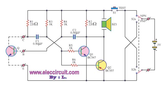
The transistor was checked by measuring the resistance between its various pins. Occasionally, issues arise when measuring the resistance between them. The process of measuring resistance in a transistor is an essential diagnostic technique used to evaluate its functionality. A...
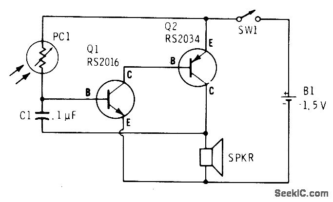
A low light condition on a cadmium sulfide photocell (Radio Shack 276-116) generates a series of clicks in a miniature 8-ohm loudspeaker. As the light intensity increases, these clicks coalesce into an audio tone that escalates in frequency with...
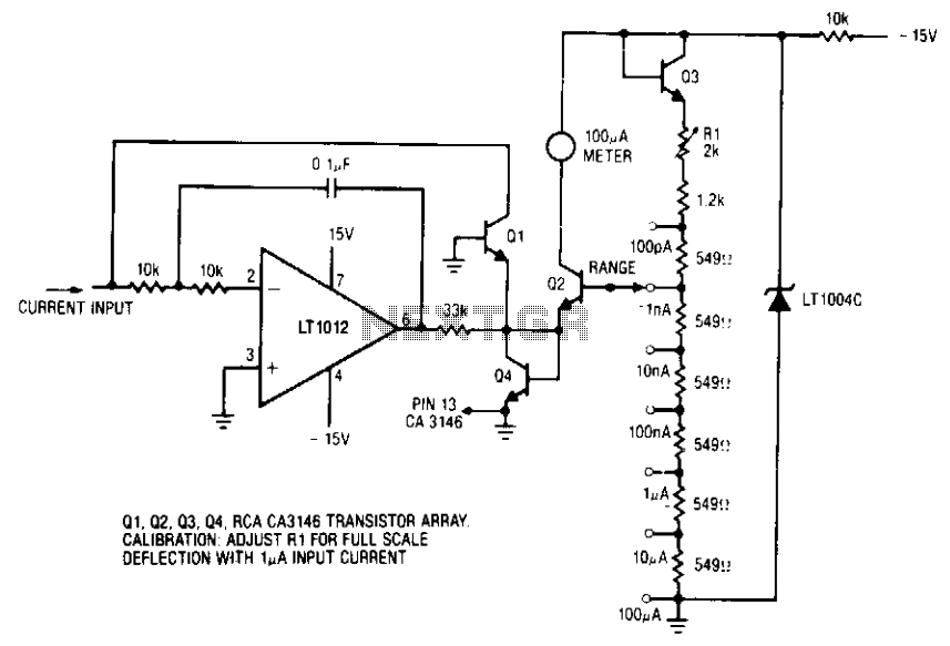
The ammeter measures currents from 100 pA to 100 µA without the use of expensive high-value resistors. Accuracy at 100 µA is limited by the offset voltage between Q1 and Q2, and at 100 pA, it is limited by...
This project is also an essential part of the expandable analyser to be published soon or perhaps eventually, and one meter circuit is used for each frequency band. There are many other uses for a simple LED VU meter....
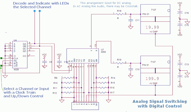
This circuit utilizes a 4052 as a DC Analog Multiplexer. The inputs to this multiplexer must originate from low-impedance output operational amplifiers (OpAmps). The resistors depicted are unnecessary once the signal conditioning OpAmps are connected. However, 100K resistors can...
When an antenna is attached, or even if not, in the presence of a strong RF field, the field strength meter has a moving coil meter to indicate relative field strength. The box holds a Schottky diode detector, a...