
Frequency meter 1KHz to 1MHz
This frequency meter circuit is designed to measure frequencies ranging from 1 Hz to 1 MHz, providing an economical solution for frequency measurement. The core of the circuit is the IC1, which is a dual Schmitt trigger (CD4583). This component acts as a signal conditioner, ensuring that the input signal is transformed into a clean square wave suitable for further processing by subsequent ICs (IC2, IC3, and IC4). The Schmitt trigger's hysteresis characteristics help in eliminating noise and ensuring stable operation.
The frequency measurement process begins with the input signal being fed into IC1. The output of IC1 is connected to the input of IC2, a counter IC (CD4026), which counts the pulses from the Schmitt trigger. For every ten pulses received, IC2 produces a carry pulse to IC3, another counter IC, which further processes this information. The first display (DIS1) shows the count from IC2, while the second display (DIS2) reflects the count from IC3. When IC3 receives its tenth pulse, it resets DIS2 to zero and increments DIS3, allowing for a total display count of up to 100.
To indicate when the measured frequency exceeds the designed limits, the carry output from IC4 activates a decimal point on DIS1, signaling that the measurement is out of range. The timing mechanism is managed by IC5, a dual timer (NE556), which controls the display duration based on the switch S1 setting—either 1 second or 1 millisecond. During this timing interval, IC5B can also produce a display interruption of 2 or 3 seconds, during which the counters and displays are turned off to conserve power.
The design emphasizes the placement of Q1, a 2N930 transistor, close to the input jack to minimize interference from high-frequency parasitic signals. Calibration of the circuit can be accomplished using a precision frequency meter and a signal generator. By setting switch S1 to the HZ position and applying a known low frequency, the trimmer potentiometer TR2 can be adjusted to ensure accurate readings. This calibration process is similarly repeated for higher frequencies in the kHz range.
The circuit is powered by a +9V battery for portability, or it can be connected to a suitable power supply if integrated into a larger system. The component list includes various resistors, capacitors, and display elements, ensuring a comprehensive approach to frequency measurement in a compact and cost-effective design.This circuit is a frequency meter, low cost. It covers region 1HZ until 1MHZ. The IC1 schmitt trigger that it regulates the signal of entry and him changes in reasonable level suitable for the IC2-3-4. With the tenth pulse in the entry of IC2/1, is produced a pulse '' carry '' in the IC3/5. The same moment the IC2 causes the depiction in the DIS1, show [0], the IC3 causes the DIS2, to show [ 1 ].
When in the entry of IC3 it reaches and the tenth pulse, the DIS2 show [ 0 ] and the DIS3 show [ 1 ], (with total depiction 100, having the display in right order). The exit '' carry'' off IC4/5, can be used in order to it turns on the decimal point (comma) the DIS1, in order to it shows a situation over the limits of measurement.
The timed begins with the one of half double timer (IC5A). Switch S1 select the interruption the time in 1sec or in 1ms. At the duration of this interruption, second half the (IC5B), it produces a interruption of depiction 2 or 3sec., at the duration which counter cut off by the entry and the displays remain OFF. In the end of depiction, a pulse RESET, begins the interruption of time/depiction. The critical point is round the Q1-IC1, which should be placed as long as it becomes more near in the jack of entry, to reject of parasitic signals of high frequency.
For the regulation, we can use a frequency meter good precision (if you do not have you are lented) and a generator of signal. We put switch S1, in place [HZ], we apply in the entry a low frequency and we regulate the trimmer TR2, so that we take the right clue, which should suit with source frequency meter.
We repeat also the regulation for the department of KHZ, with a higher frequency. The supply of circuit becomes with a battery +9V, if it is used as portable or from suitable power supply if it is incorporated in some unit that exists already. Part List R1= 8.2Mohm C5= 2.2uF 16V IC2-3-4= 4026 R2-9= 100Kohm C6= 10uF 16V IC5= 556 R3= 470Kohm C7= 10nF 63V Mylar IC6= 4007 R4= 470 ohm C8-10= 1nF 63V Mylar IC7= 7805 R5-6-7= 10Kohm C9= 1uF 16V DS1-3=Display 7segment Comm.
Cath. R8= 3.3Mohm TR1= 1M ohm trimmer S1= ON-OFF mini switch C1-2= 1uF 63V Mylar TR2= 1Kohm trimmer S2= 1X2 mini switch C3= 47uF 16V Q1= 2N930 C4= 100nF 63V IC1= 4583 [Dual Schmitt Trigger] 🔗 External reference
Related Circuits
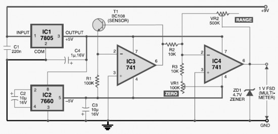
This DIY digital thermometer circuit can measure temperatures up to 150°C with an accuracy of ±1°C. The temperature is displayed on a 1V full scale deflection. The digital thermometer circuit is designed to provide accurate temperature readings within a specified...
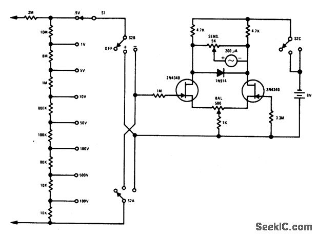
The FETVM serves as a replacement for the VTVM, eliminating the need for a conventional line cord. It features significantly improved drift rates compared to vacuum tube circuits, enabling a full-scale range of 0.5 volts, which is typically unfeasible...
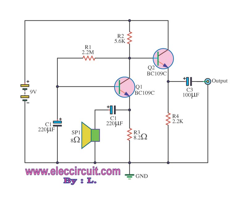
This may appear to be a basic inquiry, but the individual is a beginner in electronics. A preamplifier has been constructed to amplify the signal from a small speaker that is utilized. The preamplifier circuit is designed to increase the...
The analog to digital sketches have been extensively covered using various components. To progress to more complex circuits and concepts, it is essential to understand these simpler ones. This tutorial will not delve as deeply as others due to...
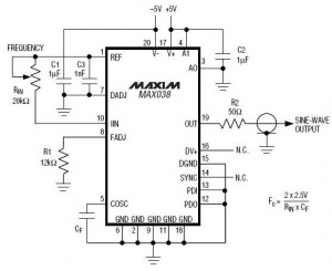
A high-frequency waveform generator is highly beneficial for electronic experimentation and design. This circuit generates sine wave oscillations; however, it can be modified to produce triangle or square wave functions. The frequency can be controlled using current. By disconnecting...
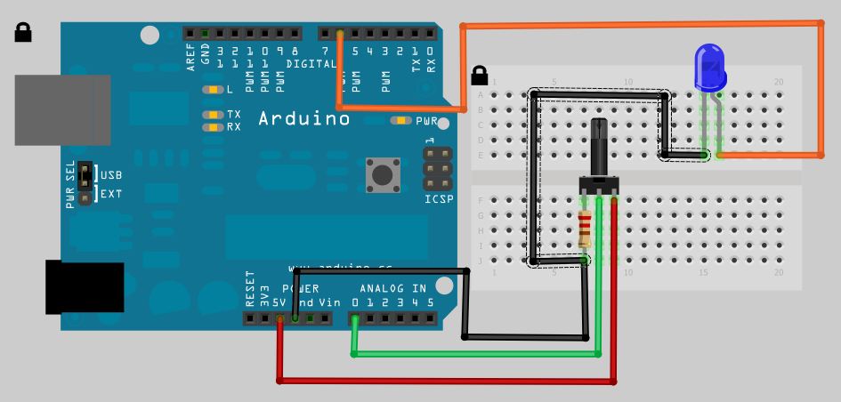
This article discusses the creation of a digital thermometer using the Arduino Uno. The temperature sensor employed is the LM35DZ, although it can be substituted with other sensors like the DS18B20. The sensor detects temperature and sends the data...