
Arduino Analog Read Potentiometer to Digital Out LED
```c
/* Analog Potentiometer to Digital LED Sketch By: David M. Orlo */
byte potPin = 0; // Analog 0 connected to the potentiometer
byte LEDPin = 6; // Connected to LED on Pin 6
int potValue = 0; // Value returned from the potentiometer
void setup() {
pinMode(LEDPin, OUTPUT); // Set Pin 6 as an Output
}
void loop() {
potValue = analogRead(potPin) / 4; // Read the potentiometer, convert to 0 - 255
analogWrite(LEDPin, potValue); // Write the converted potentiometer value to LED pin
}
```
The simplicity of this circuit is evident. To modify the functionality, the LED can be programmed to pulse in relation to the potentiometer value while maintaining the same circuit layout. The code adjustments are as follows:
```c
/* Analog Potentiometer to Digital LED Sketch By: David M. Orlo */
byte potPin = 0; // Analog 0 connected to the potentiometer
byte LEDPin = 6; // Connected to LED on Pin 6
int potValue = 0; // Value returned from the potentiometer
void setup() {
pinMode(LEDPin, OUTPUT); // Set Pin 6 as an Output
}
void loop() {
potValue = analogRead(potPin); // Read the potentiometer
digitalWrite(LEDPin, HIGH); // Turn the LED on
delay(potValue); // Use the potentiometer value as a length of time to pause the microcontroller
digitalWrite(LEDPin, LOW); // Turn the LED off
delay(potValue); // Use the potentiometer value as a length of time to pause the microcontroller
}
```
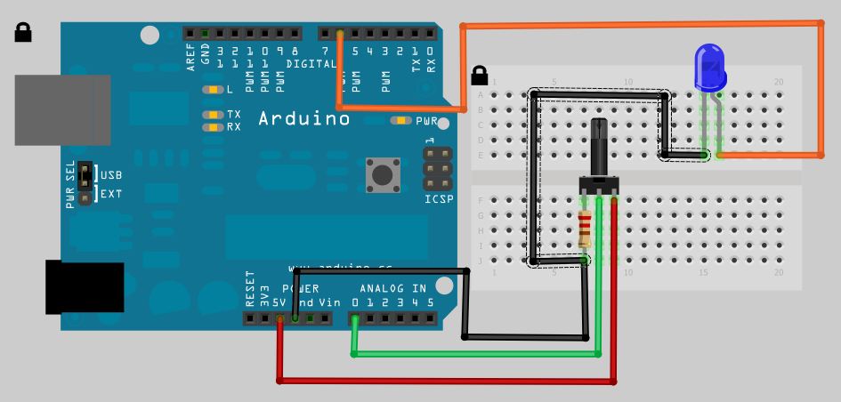
The behavior observed is that the LED blinks faster when the potentiometer is turned to the left, which may seem counterintuitive. Adjustments can be made either in the code or through hardware modifications, as previously hinted regarding the potentiometer. It is also noted that a 1K resistor is utilized instead of the 10K resistor commonly found in other examples. In the scenario where the LED blinks faster as the photoresistor darkens, reversing the GND and POS connections and substituting the 1K resistor with a 10K resistor will achieve the desired effect of slower blinking.The analog to digital sketches have been covered a million ways from Sunday with every conceivable part but in order for us to move on to more complex circuits and concepts I need to be sure you know these simpler ones. This tutorial wont be quite as in depth as the others because frankly there just isn`t much code. Without further delay I give yo u the wiring diagram. Another very simple circuit diagram, by the way if you have been wondering what program I am using for these diagram and its actually the most widely used program fordiagrammingArduino circuits, its called Fritzing and you can get it here. Its completely Free and has tons of well known parts either built in directly or available for download on the user submission pages.
As shown above the Analog signal is positive and as the positive input increases the digital output increases as well. There is of course a pull down resistor in place which is directly connected to the potentiometer, an interested side note and the reason for the 3 legs on the potentiometer is that you can swap the positive and negative in the diagram above and the LED will get brighter when you turn the potentiometer to the left (CCW) instead of the right (CW).
/* Analog Potentiometer to Digital LED Sketch By: David M. Orlo */ byte potPin=0; //Analog 0 connected to the potentiometer byte LEDPin=6; //Connected to LED on Pin 6 int potValue=0; //Value returned from the potentiometer void setup(){ pinMode(LEDPin, OUTPUT); //Set Pin 6 as an Output } void loop(){ potValue = analogRead(potPin)/4; //Read the potentiometer, convert it to 0 - 255 analogWrite(LEDPin, potValue); //Write the converted potentiometer value to LED pin } So simple isn`t it Now lets change things up a bit and make the LED pulse in relation to the potentiometer value. We can keep the same circuit layout but we need to make a few tweaks to the code. /* Analog Potentiometer to Digital LED Sketch By: David M. Orlo */ byte potPin=0; //Analog 0 connected to the potentiometer byte LEDPin=6; //Connected to LED on Pin 6 int potValue=0; //Value returned from the potentiometer void setup(){ pinMode(LEDPin, OUTPUT); // Set Pin 6 as an Output } void loop(){ potValue = analogRead(potPin); //Read the potentiometer digitalWrite(LEDPin, HIGH); //Turn the LED on delay(potValue); //Use the potentiometer value as a length of time to pause the micro digitalWrite(LEDPin, LOW); //Turn the LED off delay(potValue); //Use the potentiometer value as a length of time to pause the micro } The first thing you will notice is that the LED blinks faster when you turn the pot to the left which seems opposite to whats intuitive, I will let you figure out how to reverse this either in code or in hardware using the hint I gave you above about the potentiometer.
The code is exactly the same so no changes needed there, You will notice I used a 1K resistor instead of a 10K thats used in other examples. In my example above you will notice the LED blinks faster as the photoresistor gets darker, lets say you want to reverse that and make it blink slower, simple just reverse the GND and POS and swap out the 1K resistor for a 10K.
🔗 External reference
Related Circuits
The bi-directional sequencer employs a 4-bit binary up/down counter (CD4516) along with two "1 of 8 line decoders" (74HC138 or 74HCT138) to create the well-known "Night Rider" display. A Schmitt Trigger oscillator generates the clock signal for the counter,...
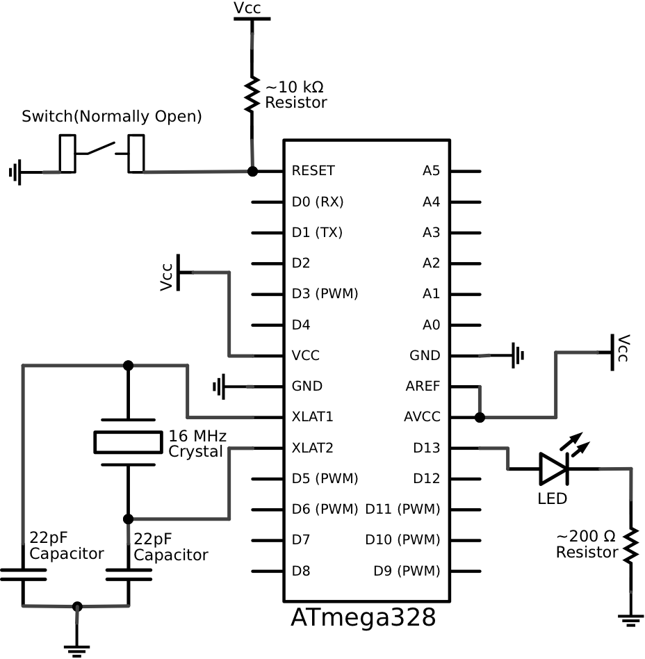
This schematic represents a minimalistic circuit that includes only the essential components required for operating an ATmega328 microcontroller with the Arduino Uno bootloader. The design of the voltage regulation circuit is left to the user. Connections to AREF and...
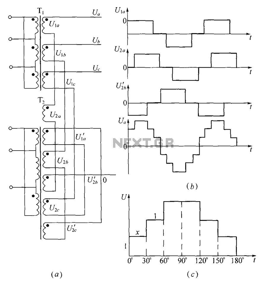
As shown, (a) for the three-phase step wave inverter output transformer winding connections; (b) in the figure, its output waveform. The three-phase step wave inverter is designed to convert direct current (DC) into a three-phase alternating current (AC) output. This...
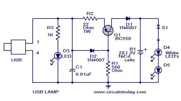
A simple USB LED lamp circuit utilizing a 5-volt power supply sourced from a USB port, designed to illuminate a desktop or laptop computer during power outages. The USB LED lamp circuit operates by converting the 5-volt DC power provided...
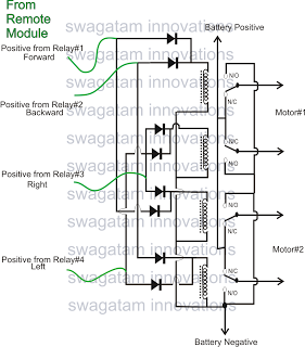
The market is filled with high-end remote-controlled toy cars; however, for hobbyists, creating one at home can be a unique experience. The following article explains how to configure a simple remote-controlled toy car using a pre-made 4-relay remote control...
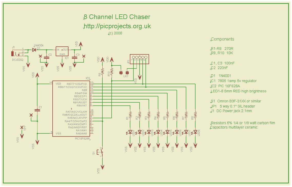
This compact circuit operates 8 LEDs directly driven from a PIC microcontroller, accompanied by a single mode control switch. The firmware controls the LEDs using a 5-bit PWM signal, enabling four levels of intensity for each LED channel: off,...
Warning: include(partials/cookie-banner.php): Failed to open stream: Permission denied in /var/www/html/nextgr/view-circuit.php on line 713
Warning: include(): Failed opening 'partials/cookie-banner.php' for inclusion (include_path='.:/usr/share/php') in /var/www/html/nextgr/view-circuit.php on line 713