
Power-line frequency meter

The described circuit functions as a frequency meter, utilizing a straightforward analog approach to convert the frequency of a power generator into a readable current output. The circuit begins with the input of sine wave signals from the power generator, which are characterized by their smooth periodic oscillations. The first stage of the circuit employs a 100K ohm resistor in conjunction with a 6.8 V zener diode to convert these sine waves into square waves. The zener diode serves to clip the peaks of the sine wave, allowing only the necessary voltage levels to pass through, while the resistor helps to limit the current and stabilize the operation of the zener.
Following the conversion to square waves, the circuit incorporates a capacitor that differentiates the square wave signal. Differentiation in this context refers to the process of measuring the rate of change of the square wave, which results in a pulse-like output that is proportional to the frequency of the incoming signal. This pulse output is then fed into a set of diodes that average the current, effectively smoothing out the fluctuations to provide a steady average current that correlates with the frequency of the input signal.
The average current produced by this stage is directly proportional to the frequency of the incoming sine waves, allowing for a simple and effective means of measuring frequency. This average current can be displayed on a 100 mA analog meter, providing a visual representation of the frequency being measured.
For calibration purposes, the circuit is designed to be connected to a 60 Hz power line. By adjusting the 5 K potentiometer, the output can be fine-tuned to ensure that the meter reads exactly 60 mA when the circuit is exposed to the standard 60 Hz frequency. This calibration step is crucial for ensuring accurate frequency measurements across different operational conditions. Overall, this circuit provides a reliable method for frequency measurement in power generation applications.The meter will indicate the frequency from a power generator. Incoming sine waves are converted to square waves by the 100K resistor and the 6,8 V zener. The square wave is differentiated by the capacitor and the current is averaged by the diodes. The average current is almost exactly proportional to the frequency and can be read directly on a 100 mA meter To calibrate, hook the circuit up to a 60 Hz poweraline and adjust the 5 K pot to read 60 mA.
Related Circuits
A function generator that operates within a frequency range of 0.1 Hz to 20 MHz can be constructed using the MAX038 integrated circuit chip. This represents a straightforward implementation of a high-performance signal generator. The MAX038 is a high-speed precision...
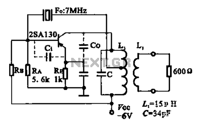
The 2SA130 transistor is used in an oscillator circuit with an oscillation frequency of 7 MHz. The power supply voltage is 6V, and the load is a frequency-selective resonant circuit with a quality factor of 600. The circuit utilizes the...
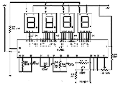
The circuit presented is a highly effective and precise digital voltmeter with an LED display utilizing the ICL7107 from Intersil. The ICL7107 is a high-performance, low-power, 3.5-digit analog-to-digital converter (ADC). This integrated circuit (IC) incorporates internal components such as...
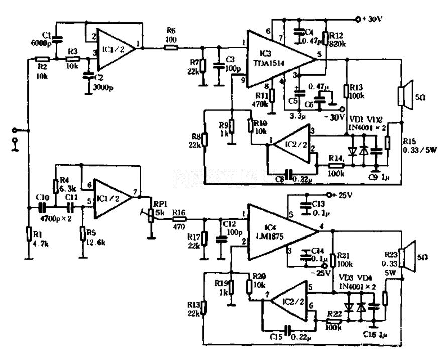
The mechanical and electrical schematic in Figure 5 illustrates a simple circuit comprising several components. The first component is an electronic crossover section utilizing the NE5532 operational amplifier, which is known as the "Emperor of the op-amp." This section...

A prerequisite for this article is that the GCC AVR programming environment is installed as described in the article "Programming the AVR microcontroller with GCC, libc 1.0.4." To avoid installation issues, using the AVR programming CD is recommended. When...

An individual sought to utilize a soldering iron to construct a frequency counter, a device that was previously absent in their lab. The schematic for the frequency counter was created using OrCAD PSpice, but the design files have since...