
Digital voltmeter using ICL7107

The ICL7107 digital voltmeter circuit is designed for versatility and precision in measuring DC voltages. The ADC's dual-slope conversion method offers high accuracy by minimizing the effects of noise and fluctuations in the input voltage. The integration phase allows for averaging the input signal, which is particularly useful in noisy environments. The choice of R2 and C1 is critical, as they determine the clock frequency that governs the speed of the ADC's operation. This frequency must be carefully selected to balance measurement speed and accuracy.
The stability of the reference voltage, enhanced by capacitor C2, is essential for reliable readings. Any fluctuations in the reference voltage can lead to significant errors in the displayed voltage, making this capacitor a vital component in the circuit. The configuration of the displays allows for clear and intuitive readings, with the leftmost display indicating polarity and overflow conditions, thus providing immediate feedback to the user.
The range control feature, implemented through resistor R4, allows the user to adapt the voltmeter to different measurement scenarios. By changing R4, the circuit can accommodate various voltage levels without requiring significant redesign. This flexibility makes the ICL7107 digital voltmeter suitable for a wide range of applications, from laboratory use to field measurements. Overall, this circuit exemplifies an efficient and practical approach to digital voltage measurement, leveraging the capabilities of the ICL7107 to deliver accurate and stable results.The circuit given here is of a very useful and accurate digital voltmeter with LED display using the ICL7107 from Intersil. The ICL7107 is a high performance, low power, 3. 5 digit analog to digital converter. The IC includes internal circuitry for seven segment decoders, display drivers, reference voltage source and a clock.
The power dissipation is less than 10mW and the display stability is very high. The working of this electronic circuit is very simple. The voltage to be measured is converted into a digital equivalent by the ADC inside the IC and then this digital equivalent is decoded to the seven segment format and then displayed. The ADC used in ICL7107 is dual slope type ADC. The process taking place inside our ADC can be stated as follows. For a fixed period of time the voltage to be measured is integrated to obtain a ramp at the output of the integrator.
Then a known reference voltage of opposite polarity is applied to the input of the integrator and allowed to ramp until the output of integrator becomes zero. The time taken for the negative slope to reach zero is measured in terms of the IC`s clock cycle and it will be proportional to the voltage under measurement.
In simple words, the input voltage is compared to an internal reference voltage and the result is converted in a digital format. The resistor R2 and C1 are used to set the frequency of IC`s internal clock. Capacitor C2 neutralizes the fluctuations in the internal reference voltage and increases the stability of the display.
R4 controls the range of the voltmeter. Right most three displays are connected so that they can display all digits. The left most display is so connected that it can display only 1 and -. The pin5(representing the dot) is connected to ground only for the third display and its position needs to be changed when you change the range of the volt meter by altering R4. (R4=1. 2K gives 0-20V range, R4=12K gives 0-200V range ). 🔗 External reference
Related Circuits
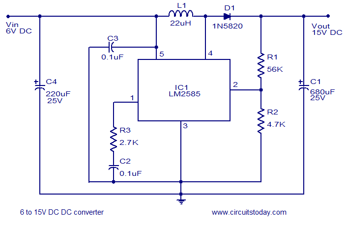
A simple and efficient 6 to 15V boost/step-up DC to DC converter based on IC L2585. This voltage converter circuit requires few external components. The circuit utilizes the L2585 integrated circuit, which is designed for high-efficiency voltage boosting applications. The...
This circuit measures temperature in Celsius scale and displays it on an alphanumeric LCD screen. When temperature rises to 40°C, an alarm is activated and at the same time a relay is also activated which drives a fan to...
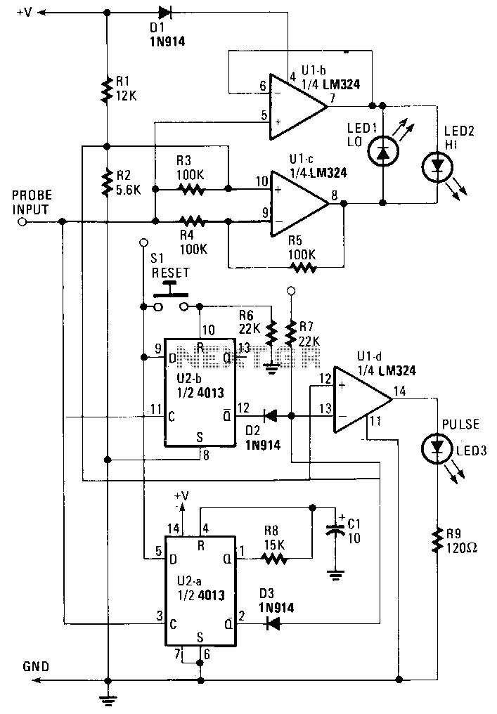
The probe operates using the power supply from the circuit under test (CUT). The input at the probe tip is divided into two pathways. One pathway directs the signal to the clock inputs of U2a and U2b. The other...
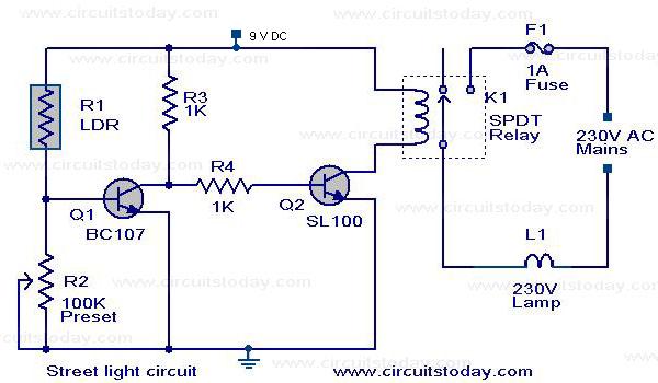
The circuit diagram of an Automatic Street Light Controller Circuit is explained in this post. The Automatic Street Light Controller Circuit is designed to automatically turn on street lights at dusk and turn them off at dawn. This functionality is...
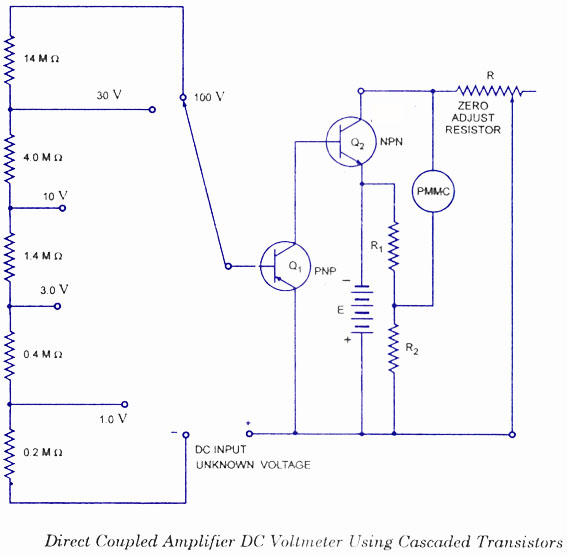
This type of voltmeter is very common due to its low cost. It is designed to measure voltages in the milli-volt range because of limited amplifier gain. The circuit diagram for a direct-coupled amplifier DC voltmeter using cascaded transistors...

This design circuit is for converting voltage to frequency. Typically, frequency meters are used in speed sensors, tachometers, and for measuring recurring signals. The frequency to voltage converter (FVC) can transform voltage into either a digital or analog tachometer....