
Frequency Counter

The frequency counter circuit is designed to accurately measure and display input signal frequencies over a specified integration period. The primary components include pulse counters, latches for data retention, control logic for sequencing operations, and indicators for overflow conditions. The input signal is fed into the counting mechanism, which tallies the number of pulses during the integration period.
In free-running mode, the device continuously counts pulses, providing real-time feedback on the input frequency. The overflow indicator serves as a critical feature, alerting the user when the count exceeds the display capabilities. The reset functionality ensures that the device can be quickly restarted after an overflow or for new measurements.
The integration period can be dynamically adjusted between 1 ms and 10 s, allowing for flexibility in measurement based on the expected frequency range. The fixed time base provides a straightforward option for standard measurements, while the variable time base allows for fine-tuning, accommodating a wider variety of input frequencies.
Control logic is implemented to manage the timing and sequencing of the counters and latches. When data hold is activated, the current count is preserved on the display, enabling users to capture and analyze transient signals without losing data. This feature is particularly useful in applications where signal characteristics may change rapidly.
The decade counters are configured to count pulses and transfer their values to latches at the end of each integration period, ensuring that the displayed value is representative of the measured frequency. The use of a rotary switch for decade selection simplifies the user interface, allowing for quick adjustments between different frequency ranges.
In summary, the frequency counter circuit is a versatile and reliable tool for measuring and displaying frequency, with features designed to enhance usability and accuracy. The combination of fixed and variable time bases, along with the ability to pause and reset the count, makes it a valuable addition to any electronics lab.I needed an excuse to use the soldering iron so I figured that I might as well as make a frequency counter which is something that I`ve always wanted, but lacked in my lab. Here`s the schematic. I drew it up in OrCAD PSpice a while back. Since then, I have lost the design files, but fortunately, I kept a hard copy, complete with annotations of the colour of the wire that I used for some of the confusing control logic.
In free running mode, the device simply counts the number of pulses that has come in from the input port. If the number of pulses exceeds what can be displayed (999999), then an overflow indicator will turn on, indicating this error.
Pressing the reset button will reset the count and the overflow indicator. Enabling data hold will pause the display while the device continues counting; no counts will be lost when data hold is enabled. Implementation: In this mode, the latches will activate (i. e. enable memory) when the data hold switch is enabled. The control logic will not reset the counters or enable the latch memory. In other words, the time base will be ignored. In frequency counter mode, the counters will count the number of pulses over a given period of time, otherwise referred to as the integration period.
The number of pulses in this period is displayed. If the integration period is 1 s, then the displayed number is the frequency of the input port in Hz. If the frequency is too high and cannot be displayed, an overflow indicator will be lit. This can be cleared by pressing the reset button. Like free running mode, the current display can be paused by flipping the data hold switch. During this time, the frequency counter is still running and the current frequency will be updated once the data hold switch is deactivated.
The frequency counter can have integration periods of anywhere between 1 ms to 10 s. The fixed time base can generate integration periods between 1 ms to 10 s in decade increments. There is also a variable time base will allows the user to continuously tune in between these frequencies as necessary. A switch is used to select between the fixed and variable time base. A rotary switch is used to select the decade of interest. Implementation: During the integration period, pulses from the input port are being counted by the decade counters.
After this period is over the contents of the counters will be copied over to the latches and thus be displayed. After being copied over to the latches, the counters themselves are cleared and the count starts accumulating again over a new integration period.
The overflow light and counter and latch contents can be cleared by pressing the reset button. The control circuit will reset the counter and enable the latches in the correct sequency as necessary. In the even of data hold being activated, the control circuit will reset the counters in the same sequence as before, but the latches will be set to retain data until data hold is disabled.
There are two time bases in the frequency counter; a fixed and a variable. The fixed time base has a period of 1 ms. Both are fed to subsequent divide by 10 counters to achieve slower integration periods up to 10 s. These controls allow the frequency counter to continuously cover integration periods between 1 ms to 10s. To facilitate changes, the circuit was first built on bread boards. Here is a picture of the design in action. During the excitement, I forgot to take pictures of the time base and control circuit. Here is the cir 🔗 External reference
Related Circuits
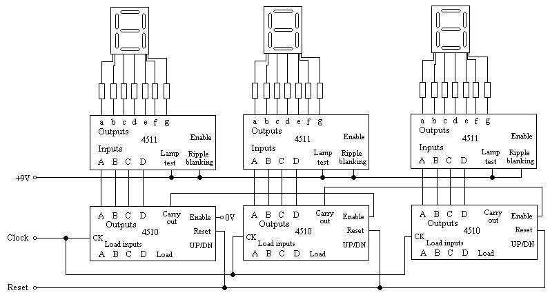
The lab project involves a BCD counter and a 7-segment display using the CD4510BMS presettable BCD Up/Down Counter. The objective is to count from 32 to 84, rather than the default range of 00 to 99. The current setup...
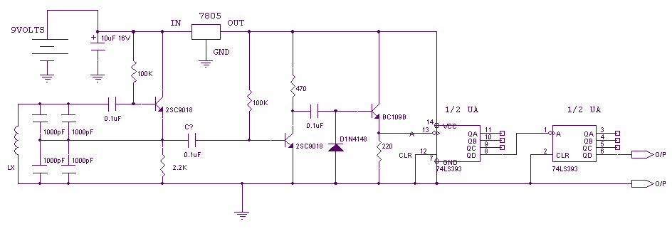
The following circuit enables measurement of the inductance of the inductor labeled LX, which is the inductance to be measured. The output of the circuit is a TTL square wave whose frequency relates to the inductance being measured. The...
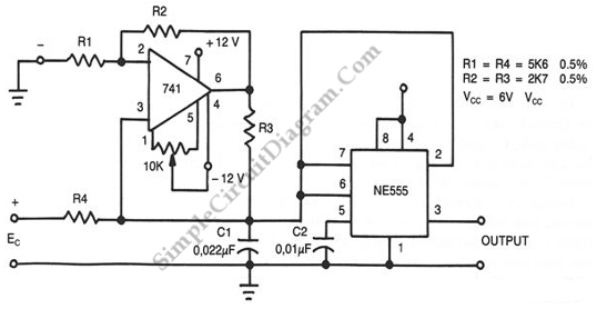
This circuit accepts positive, negative, or differential control voltages. When the control voltage is zero, the output frequency is also zero. The described circuit functions as a versatile control voltage interface, capable of processing a range of input signals, including...
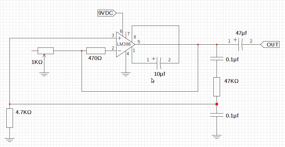
The design utilizes the LM386n-1 integrated circuit, powered by a single power supply to maintain a compact layout. There is a need to control the frequency, and the user is inquiring about which component values should be adjusted for...
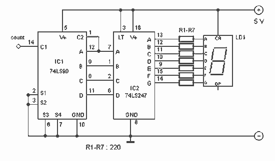
With this counter you can count laps for example (in conjunction with the Simple light trap). The circuit uses two TTL ICs 74LSxx the series. The left IC is a decimaalteller. The input pulses 14 are counted and converted...

The meter utilizes time averaging to generate a direct current that is proportional to the frequency of the input signal. The described meter operates on the principle of time averaging, which is a method used in electronic measurement systems to...