
Programmable voltage controlled timer
The µA2240 integrated circuit is designed to function as a versatile programmable timer, leveraging its internal architecture to deliver precise timing functions with minimal component requirements. The key feature of this device is its modulation input, which facilitates external control over the timing characteristics. By connecting a variable voltage from a potentiometer, users can dynamically adjust the input threshold, allowing for flexible timing applications.
The time base output (TBO) is a critical component of the µA2240's functionality. It operates in an open-collector configuration, which allows for easy interfacing with other digital circuits. The inclusion of a 10 kΩ pull-up resistor ensures that the output can be reliably pulled high when not actively driven low by the TBO. This configuration not only enhances signal integrity but also enables the TBO to drive subsequent logic stages, such as the 8-stage counter, effectively expanding the timer's capabilities.
Upon receiving a positive trigger pulse at startup, the TBO initiates its timing cycle, resetting all counter outputs to a low state. The open-collector nature of the counter outputs allows for a "wired-OR" logic configuration, where multiple outputs can be combined to generate a single output signal. This feature is particularly useful in applications requiring multiple timing conditions to be monitored simultaneously.
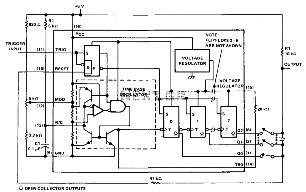
The µA2240's architecture supports the generation of up to 255 discrete time delays, each corresponding to integer multiples of the time-base period. This is accomplished by summing the binary outputs of the counter, providing a flexible method for achieving various timing requirements. The range of delays, from 200 µs to 0.223 s, makes the µA2240 suitable for a wide range of timing applications in both consumer and industrial electronics. Overall, the µA2240 presents a robust solution for programmable timing needs, combining ease of use with extensive functionality.The µA2240 may easily be configured as a programmable voltage controlled timer with a minimum number of external components. The modulation input (pin 12), which allows external adjustment of the input threshold level. A variable voltage is applied from the arm of a 10 k ohm potentiometer connected from Vcc to ground. A change in the modulation input voltage will result in a change in the time base oscillator frequency and the period of the time base output (TBO).
The TBO has an open-collector output that is connected to the regulator output via a 10 k ohm pull-up resistor. The output of the TBO drives the input to the 8-stage counter section. At start-up, a positive trigger pulse starts the TBO and sets all counter outputs to a low state. The binary outputs are open-collector stages that may be connected together to the 10 k ohm pull-up resistor to provide a "wired-OR" output function. This circuit may be used to generate 255 discrete time delays that are integer multiples of the time-base period.
The total delay is the sum of the number of time-base periods, which is the binary sum of the Q outputs connected. Delays from 200 µß to 0.223 s are possible with this configuration. 🔗 External reference
Related Circuits
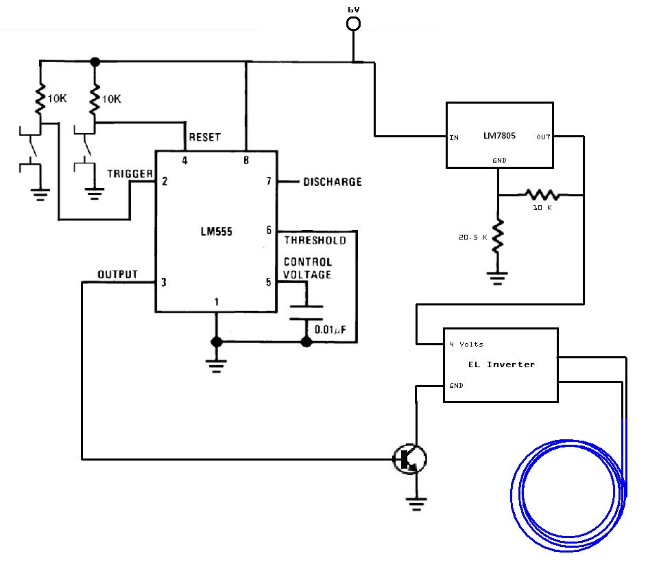
The circuit utilized for this project is quite simple. Some may criticize the omission of decoupling capacitors for the LM7805 voltage regulator. The circuit in question employs the LM7805 voltage regulator, which is designed to provide a stable output voltage...
This low voltage circuit can be used to monitor batteries and other volatile sources of current for problems. The circuit sounds an alarm and lights an LED, but can be interfaced to any number of other circuits for many...
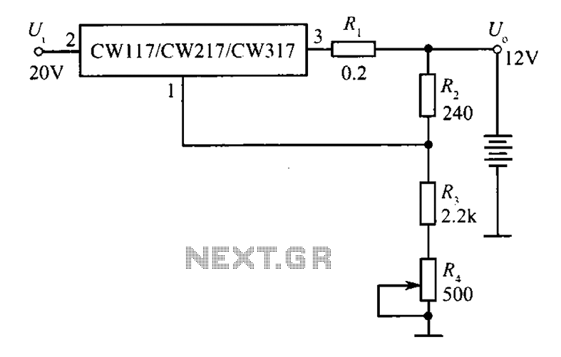
A 12V constant voltage charger is depicted. The power supply circuit shares the same basic design. The resistor R1, valued at 0.2 ohms, serves a limiting function, effectively increasing the internal resistance of the charger, which in turn reduces...
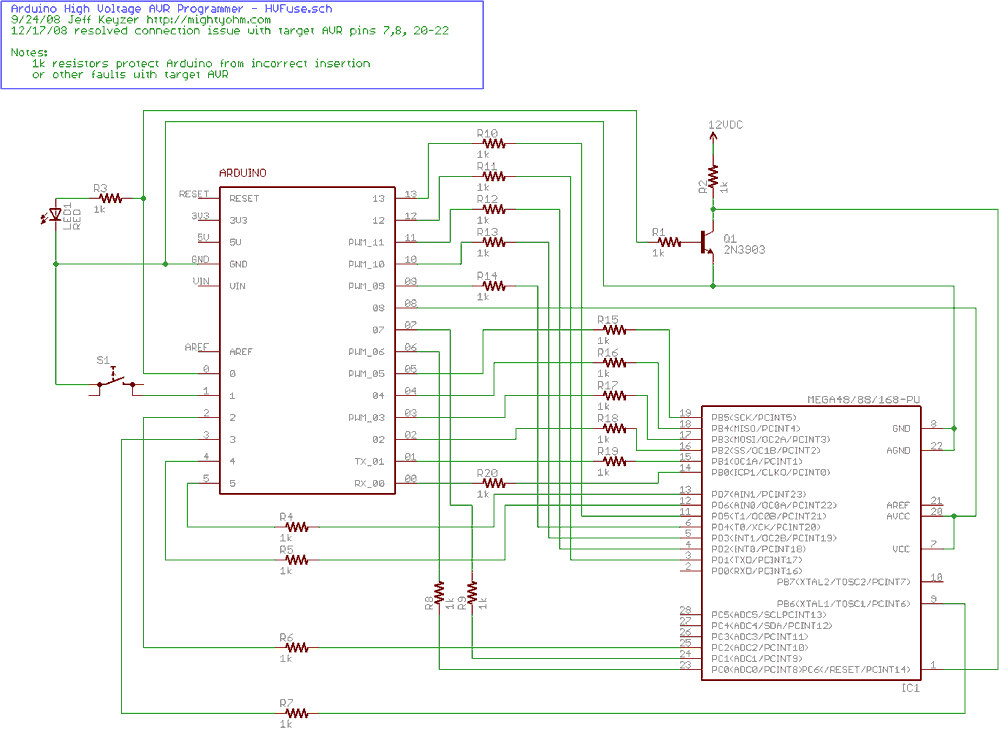
Fortunately, my trusty Arduino came to the rescue. I created an Arduino-based AVR programmer that uses the high voltage programming mode and can fix pesky fuses like RSTDISBL. The Arduino has just enough IO to implement the entire HV...
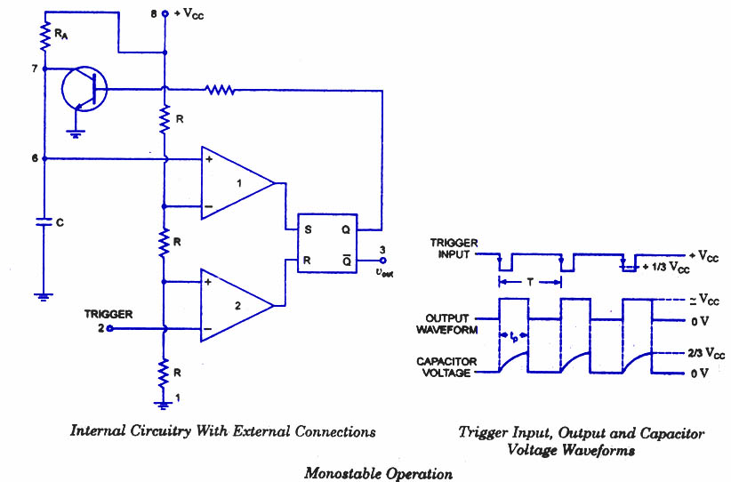
Are you familiar with the basics and applications of the 555 timer IC? Are you looking for a book that provides all these basics? If so, CircuitsToday has started an online store where you can purchase books on the...
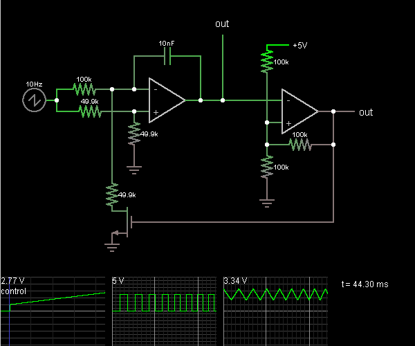
This circuit is a voltage-controlled oscillator, which is an oscillator whose frequency is determined by a control voltage. A 10 Hz sawtooth oscillator provides the control voltage in this case; this causes the frequency to rise slowly until it...