
Low Voltage Alarm
The low voltage monitoring circuit is designed to provide real-time feedback on the status of batteries and other current sources, ensuring that any irregularities in voltage levels are detected promptly. The circuit typically consists of a voltage divider, a comparator, an LED indicator, and a sound alarm, which can be integrated into a broader system.
The voltage divider is formed by two resistors connected in series across the battery or current source. This configuration reduces the voltage to a manageable level for the comparator, which is the heart of the monitoring system. The comparator is set to a reference voltage that corresponds to the acceptable range for the battery voltage. When the voltage from the battery falls below this threshold, the comparator output changes state.
The output of the comparator is connected to a transistor, which acts as a switch. When the comparator detects a low voltage condition, it turns on the transistor, allowing current to flow through the LED and the alarm circuit. The LED illuminates to provide a visual indication of the problem, while the alarm sounds to alert users to the issue.
Additionally, the circuit can be designed to interface with other systems. For instance, it can send a signal to a microcontroller or a more complex alarm system for further processing or logging of the event. This flexibility allows the circuit to be customized for various applications, including battery management systems, power supply monitoring, and other safety-critical environments.
Overall, this low voltage monitoring circuit is a versatile and essential tool for ensuring the reliability and safety of battery-operated devices and other electronic systems.This low voltage circuit can be used to monitor batteries and other volatile sources of current for problems. The circuit sounds an alarm and lights an LED, but can be interfaced to any number of other circuits for many different uses.
🔗 External reference
Related Circuits
Transistors are configured as a Darlington pair in this circuit. A thermistor is utilized to detect or sense heat. A 12K variable resistor is employed to adjust the activation of the buzzer at the desired temperature. The operation of...
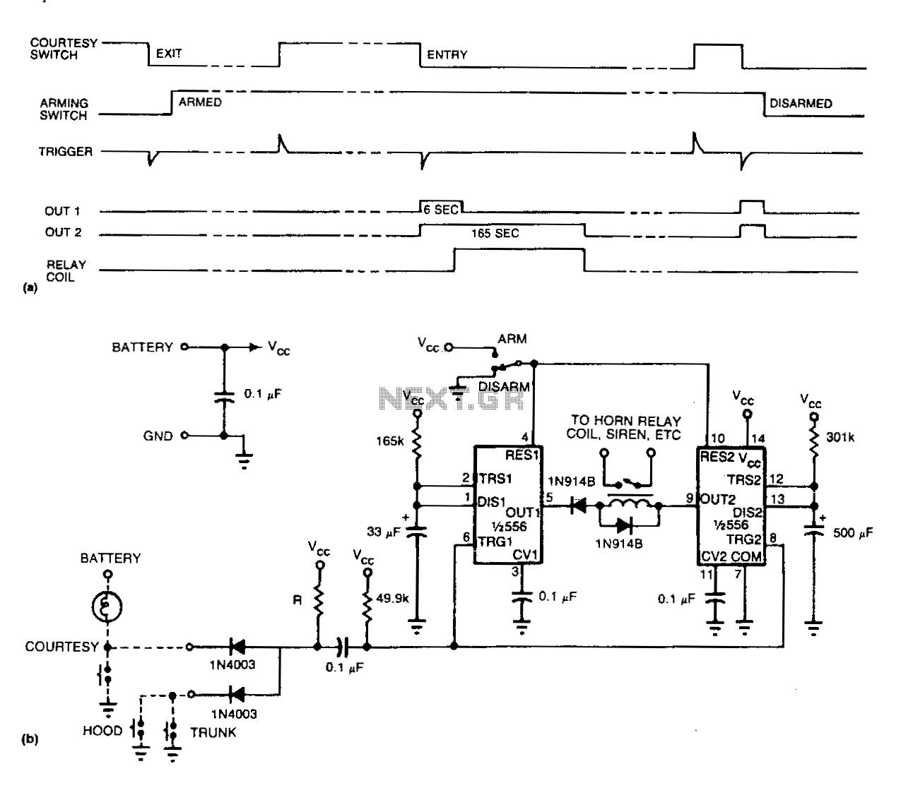
Refer to (a) for the timing information related to the alarm circuit depicted in (b). When departing from the vehicle, the arming switch should be flipped, and the door closed to activate the device. The subsequent opening of an...
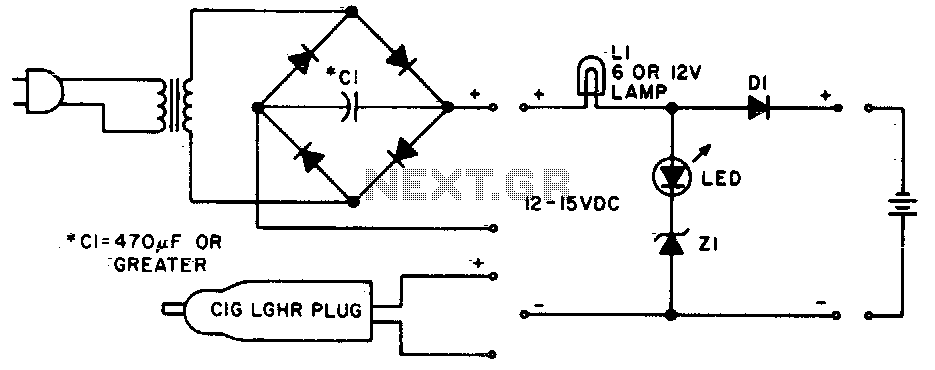
Lamp LI will glow brightly while the LED remains off when the battery is low and charging. Conversely, the LED will illuminate brightly, and the light bulb will be dim when the battery is nearly charged. Lamp LI should...

This circuit is a slight modification of a previous design. In the earlier version, the switch needed to be held down for the entire duration of the music playback. In this updated circuit, pressing the push button once charges...

The circuit detailed in this document is designed to produce up to 30 kilovolts or more from a low-voltage DC source using a flyback transformer (LOPT) salvaged from a black-and-white or color television or computer monitor. With a typical...
If you are looking for ICs for a DC to DC converter application, the LM1577/LM2577 ICs are highly recommended as they provide all the necessary power and control functions for step-up conversion. The LM1577 and LM2577 are versatile integrated circuits...
Warning: include(partials/cookie-banner.php): Failed to open stream: Permission denied in /var/www/html/nextgr/view-circuit.php on line 713
Warning: include(): Failed opening 'partials/cookie-banner.php' for inclusion (include_path='.:/usr/share/php') in /var/www/html/nextgr/view-circuit.php on line 713