
555 Timer as Monostable Multivibrator
The 555 timer IC, particularly in its monostable mode, serves a critical function in various electronic applications, including timers, pulse generation, and frequency division. The monostable multivibrator configuration allows for the generation of a single output pulse in response to an input trigger. The pulse width, which can be adjusted by varying the resistor (RA) and capacitor (C) values, provides flexibility in timing applications.
In practical implementations, the 555 timer is often used in conjunction with other components to create sophisticated timing circuits. For instance, it can be paired with additional resistors and capacitors to create a delay timer that can control the operation of other devices, such as motors or LED indicators. Additionally, the output signal can be interfaced with other logic circuits, enabling the 555 timer to function as part of larger systems, such as alarms, sensors, and control systems.
The reliability and ease of use of the 555 timer make it a staple in both educational settings and professional engineering applications. Its ability to produce precise timing intervals and its robustness under various operating conditions contribute to its widespread adoption in electronic design. Understanding the principles and applications of the 555 timer IC is essential for anyone involved in electronics, whether for hobbyist projects or industrial applications.Are you familiar with the basics and applications of the 555 timer IC Are you looking for a book that provides all these basics If so, CircuitsToday has started an online store from where you can buy books on 555 timer IC, which have been reviewed in detail. You can go through the reviews and buy them here:- 3 Great Books to Learn 555 Timer Circ uits and Projects A monostable multivibrator (MMV) often called a one-shot multivibrator, is a pulse generator circuit in which the duration of the pulse is determined by the R-C network, connected externally to the 555 timer. In such a vibrator, one state of output is stable while the other is quasi-stable (unstable). For auto-triggering of output from quasi-stable state to stable state energy is stored by an externally connected capaci tor C to a reference level.
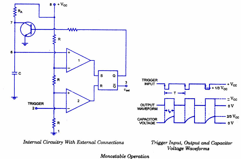
The time taken in storage determines the pulse width. The transition of output from stable state to quasi-stable state is accom plished by external triggering. The schematic of a 555 timer in monostable mode of operation is shown in figure. Pin 1 is grounded. Trigger input is applied to pin 2. In quiescent condition of output this input is kept at + VCC. To obtain transition of output from stable state to quasi-stable state, a negative-going pulse of narrow width (a width smaller than expected pulse width of output waveform) and amplitude of greater than + 2/3 VCC is applied to pin 2.
Output is taken from pin 3. Pin 4 is usually connected to + VCC to avoid accidental reset. Pin 5 is grounded through a 0. 01 u F capacitor to avoid noise problem. Pin 6 (threshold) is shorted to pin 7. A resistor RA is connected between pins 6 and 8. At pins 7 a discharge capacitor is connected while pin 8 is connected to supply VCC. Initially, when the output at pin 3 is low i. e. the circuit is in a stable state, the transistor is on and capacitor- C is shortedto ground. When a negative pulse is applied to pin 2, the trigger input falls below +1/3 VCC, the output of comparator goes high which resets the flip-flop and consequently the transistor turns off and the output at pin 3 goes high. This is the transition of the output from stable to quasi-stable state, as shown in figure. As the discharge transistor is cut off, the capacitor C begins charging toward +VCC through resistance RA with a time constant equal to RAC.
When the increasing capacitor voltage becomes slightly greater than +2/3 VCC, the output of comparator 1 goes high, which sets the flip-flop. The transistor goes to saturation, thereby discharging the capacitor C and the output of the timer goes low, as illustrated in figure.
The output of the Monostable Multivibrator remains low until a trigger pulse is again applied. Then the cycle repeats. Trigger input, output voltage and capacitor voltage waveforms are shown in figure. where RA is in ohms and C is in farads. The above relation is derived as below. Voltage across the capacitor at any instant during charging period is given as The pulse width of the circuit may range from micro-seconds to many seconds. This circuit is widely used in industry for many different timing applications. 🔗 External reference
Related Circuits
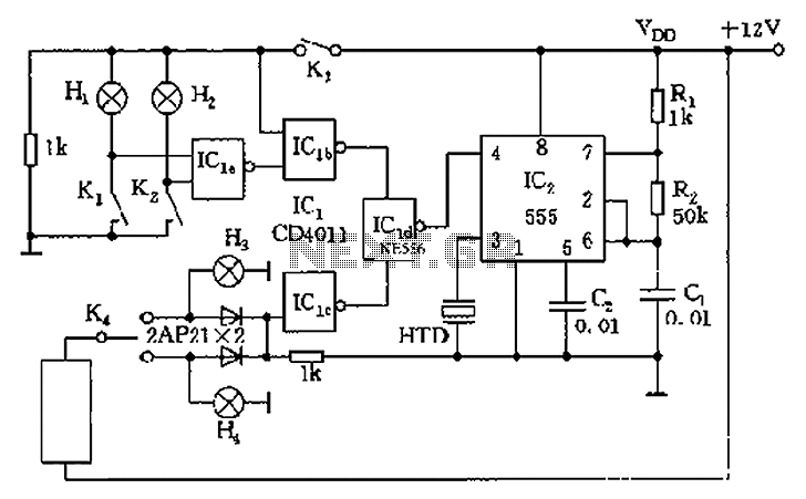
The circuit presented is a 555 timer-based alarm system for vehicles, which primarily consists of a 555 timer and a quad 2-input NAND gate configuration. It is designed to produce a long beep sound when oil pressure is low...

The FM modulator circuit is a straightforward FM modulation design utilizing the IC 555, where the resulting modulated signal is dependent on the frequency of the input signal. The output signal is stable and of good quality, eliminating the...
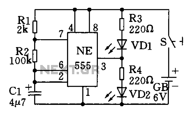
The circuit utilizes a 555 timer as the central component of a flashing light circuit. In normal operation, the light-emitting diodes (LEDs) VD1 and VD2 alternate flashing. The circuit comprises the NE555 timer, resistors R1 and R2, and capacitor...
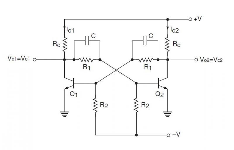
Multivibrators, unlike sinusoidal oscillators, are circuits with regenerative feedback that produce pulsed outputs. There are three primary types of multivibrators: the Bistable Multivibrator, the Monostable Multivibrator, and the Astable Multivibrator. A bistable multivibrator circuit maintains stable LOW and HIGH...
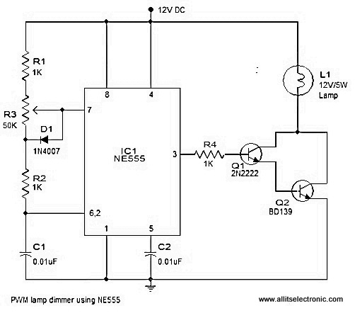
A simple and efficient PWM lamp dimmer utilizing the timer IC NE555 is presented in this article. Traditional linear regulator-based dimmers achieve a maximum efficiency of only 50%, which is significantly lower than PWM-based dimmers that can exceed 90%...
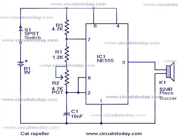
This cat and dog repeller circuit is designed to deter animals from specific areas. The circuit utilizes ultrasonic sound, which is known to provoke a strong response in many animals, particularly cats. The design features an astable multivibrator configuration...