Clock pulse generator for CMOS
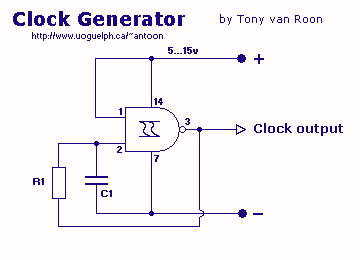
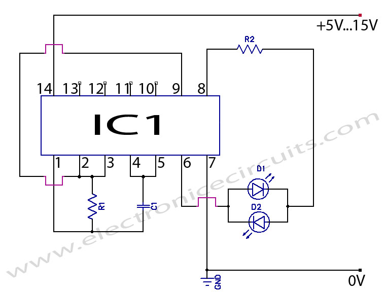
Excellent clock generator to drive 4017 type cmos circuits. R1 = 10K to 10M, C1 = 100pF to 47uF. Fo is ±1Kz when R1=100K and C1=10nF. Input voltage can be from 5 to 15V.
The described clock generator circuit is designed to provide a stable clock signal for driving CMOS circuits, specifically the CD4017 decade counter. The circuit utilizes a resistor (R1) and a capacitor (C1) to establish the oscillation frequency, which is crucial for the operation of the connected CMOS devices.
The resistor R1 can be selected between 10K ohms to 10M ohms, allowing for flexibility in tuning the frequency of the generated clock signal. The capacitor C1 can be chosen from a range of 100 picofarads (pF) to 47 microfarads (μF), which also directly influences the timing characteristics of the oscillator. The relationship between R1, C1, and the output frequency (Fo) of the generator is such that when R1 is set to 100K ohms and C1 to 10nF, the output frequency is approximately ±1KHz.
The input voltage range for this clock generator is specified from 5V to 15V, which accommodates a variety of power supply options, making the circuit versatile for different applications. The design is likely based on a simple astable multivibrator configuration, possibly utilizing a 555 timer IC or a similar oscillator circuit, which provides a square wave output.
In practical applications, this clock generator can be used not only with the CD4017 but also with other CMOS logic devices that require a clock input for synchronous operation. The ability to adjust the frequency makes it suitable for various timing applications, including LED flashing, frequency division, and other timing-related tasks in electronic projects. Proper selection of R1 and C1 values is essential to achieve the desired frequency and stability in the output signal.Excellent clock generator to drive 4017 type cmos circuits. R1 = 10K to 10M, C1 = 100pF to 47uF. Fo is ±1Kz when R1=100K and C1=10nF. Input voltage can be from 5 to 15V. 🔗 External reference
