
Measuring phase difference

The circuit is tested for sinusoidal inputs and indicates a linearity within 1%. Measurements are unaffected by the frequency of the inputs up to 75 kHz.
The described circuit employs a method for phase measurement that is both effective and precise. The primary components include square wave generators, a D flip-flop, an EX-OR gate, and an amplifier. The square waves, designated as A and B, are generated to represent two distinct signals whose phase relationship is to be analyzed. The D flip-flop serves as a critical element in determining the leading or lagging nature of the input signals. It outputs logic 1 when signal A leads signal B and logic 0 when the opposite occurs.
The output from the D flip-flop, labeled as C, is fed into an amplifier, which is responsible for producing a proportional output based on the phase difference between the two input signals. When C is at logic 0, indicating that input A is lagging behind input B, the amplifier's output F is positive. Conversely, when C is at logic 1, indicating that input A is leading input B, the output F becomes negative. This dual-output mechanism allows for clear differentiation between leading and lagging phases, facilitating accurate phase measurement.
The circuit has been rigorously tested with sinusoidal inputs, demonstrating a linearity of within 1%. This indicates that the circuit maintains consistent performance across a range of input conditions. Additionally, the design is robust against variations in frequency, sustaining accurate measurements for input frequencies up to 75 kHz. This capability makes the circuit suitable for various applications in electronic measurement and control systems, where precise phase information is critical.This method is capable of measuring phase between 0 to ±180°. The generated square waves A and are fed to a D flip-flop which gives an output C equal to logic 1 when input 1 leads input 2 and equal to logic 0 in case of lagging. When C = logic 0, the output of the amplifier F will be positive proportional to the average value of the output of the EX-OR.
When C = logic 1, F will be negative and also proportional to by the same factor. Hence, the output of the meter is positive in case of lagging and negative for leading. The circuit is tested for sinusoidal inputs and indicates a linearity within 1%. Measurements are unaffected by the frequency of the inputs up to 75 kHz.
Related Circuits
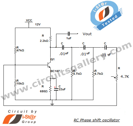
This section introduces a transistor oscillator circuit known as the RC Phase Shift Oscillator. An oscillator is an electronic circuit that functions as a sine wave generator, requiring only a DC power supply. It is commonly used in variable...
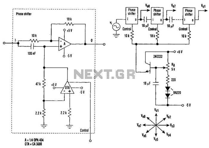
The circuit consists of eight cascaded identical cells, each cell being a DC-controlled active phase shifter. Since the DC control is common for all shifters, the circuit is adjusted by tuning resistor RA so that the phase difference between...
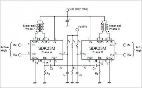
The Star Delta starting method is a motor starting mechanism that minimizes the large amount of starting current drawn by motors. As the name suggests, the Star Delta method involves supplying the motor with 1/sqrt(3) (approximately 58%) of the...
The SM5023 series consists of 3rd overtone crystal oscillator module integrated circuits (ICs). These ICs are equipped with built-in oscillator capacitors that provide excellent frequency response. The cutoff frequency can be configured using an external feedback resistor (Rfo), allowing...
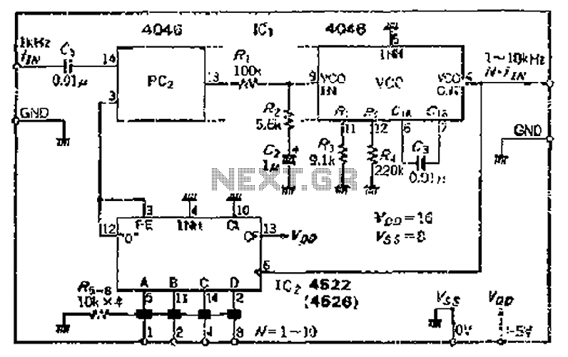
The CMOS IC 4046 Phase-Locked Loop (PLL) operates with a maximum frequency of 1 MHz. It is connected to a programmable divider, allowing it to process input frequencies. As the frequency increases by a factor of t, the circuit's...

This is a simple design schematic for a phase control circuit that regulates the power delivered to an AC load. The phase control circuit modifies the AC waveform, allowing for variations such as full cycle, half cycle, zero cycle,...