
Using PLL Phase Locked Loop IC frequency N 1 to 10 of the multiplier circuit
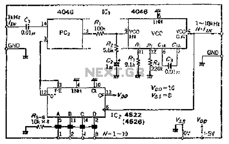
The CMOS 4046 PLL is a versatile integrated circuit designed for frequency synthesis and demodulation applications. The primary components of the 4046 include a phase comparator, a voltage-controlled oscillator (VCO), and a programmable frequency divider. The phase comparator can operate in two modes, PC1 and PC2, which allow for different applications depending on the desired output characteristics.
In operation, the VCO generates an output frequency that is adjustable based on the input control voltage. The programmable divider allows for the division of the VCO output frequency, enabling the PLL to lock onto a specific frequency ratio. The phase comparator continuously monitors the phase difference between the divided output frequency and the reference input frequency. When a phase discrepancy is detected, the phase comparator generates an error signal that is filtered by the loop filter (consisting of resistors and capacitors) to smooth out the control voltage applied to the VCO.
The loop filter's design is crucial for the stability and performance of the PLL. It determines the response time and bandwidth of the system, affecting how quickly the PLL can lock onto a new frequency. The choice of resistor and capacitor values in the loop filter must be carefully calculated to achieve the desired transient response and steady-state performance.
The VCO's frequency range is defined by the input voltage, which can be adjusted to cover a wide range of frequencies, making the 4046 suitable for various applications, including frequency modulation, demodulation, and clock recovery in communication systems.
Additionally, attention must be given to potential circuit errors that can arise from component tolerances, noise, and temperature variations. Implementing design strategies to mitigate these issues, such as using precision components and providing adequate thermal management, can significantly improve the long-term stability and reliability of the PLL circuit. C- MOSIC4046 PLL having the main function of a maximum operating frequency of iMHz integrated circuit, which is connected to the programmable divider, can constitute the input frequency increases t times the circuit. Phase comparator PC2 check, t phase 1 is equal to the frequency of the output of the frequency divider circuit and t which outputs ) ~ vP-P signal via the loop filter (roar -R2, G soap) after filtering vco oscillation frequency control. vco variable range of jf a field -f, In is from the input frequency fiv to N- ffw. Consider Journal circuit errors and long-term stability, actually increase the number of safety margin.
Related Circuits
This module, available in a Stainless DIL 8 configuration, can independently measure four analog voltages ranging from 0 to 5 volts and transmit the results as four characters over a standard asynchronous serial link. Its serial output is compatible...
This is a complete alarm system with five independent zones suitable for a small office or home environment. It utilizes three CM integrated circuits and features a timed entry/exit zone, four immediate zones, and a panic button. There are...
A low-frequency test oscillator designed for testing tone controls and conducting experiments. The low-frequency test oscillator serves as a versatile tool in audio engineering, particularly for evaluating tone control circuits and facilitating various audio experiments. This device generates sinusoidal waveforms...
The piezo diaphragm can originate from a music card, and if two or three diaphragms are available, they can be connected in parallel, as illustrated in the diagram, to observe their impact on the output frequency. The only component...

The robot requires a method for detecting obstacles (or other robots) without making physical contact. This capability allows the robot to determine whether to avoid or confront and investigate the obstacle based on its programming. This document outlines the...
The current application involves the use of the VHDL hardware description language for designing a traffic light system controller circuit. This design is implemented within the Altera MAX PLUS EDA software environment, which facilitates compilation, simulation, and programming for...
Warning: include(partials/cookie-banner.php): Failed to open stream: Permission denied in /var/www/html/nextgr/view-circuit.php on line 713
Warning: include(): Failed opening 'partials/cookie-banner.php' for inclusion (include_path='.:/usr/share/php') in /var/www/html/nextgr/view-circuit.php on line 713